Mechanical truck-unloading device

A mechanical and truck technology, applied in the direction of lifting devices, etc., can solve the problems of easy safety accidents and slow unloading speed of trucks, and achieve the effect of preventing movement and speeding up unloading speed

Inactive Publication Date: 2018-11-13
JINYIMENG GRP CO LTD
View PDF7 Cites 8 Cited by
  • Summary
  • Abstract
  • Description
  • Claims
  • Application Information

AI Technical Summary

Problems solved by technology

[0004] In order to overcome the disadvantages of slow unloading speed of trucks and easy occurrence of safety accidents during unloading in the prior art, the technical problem to be solved is: to provide a mechanical unloading equipment for trucks that speeds up the unloading speed of trucks and makes unloading safe

Method used


Image

  • Mechanical truck-unloading device
  • Mechanical truck-unloading device
  • Mechanical truck-unloading device

Examples


Embodiment 1

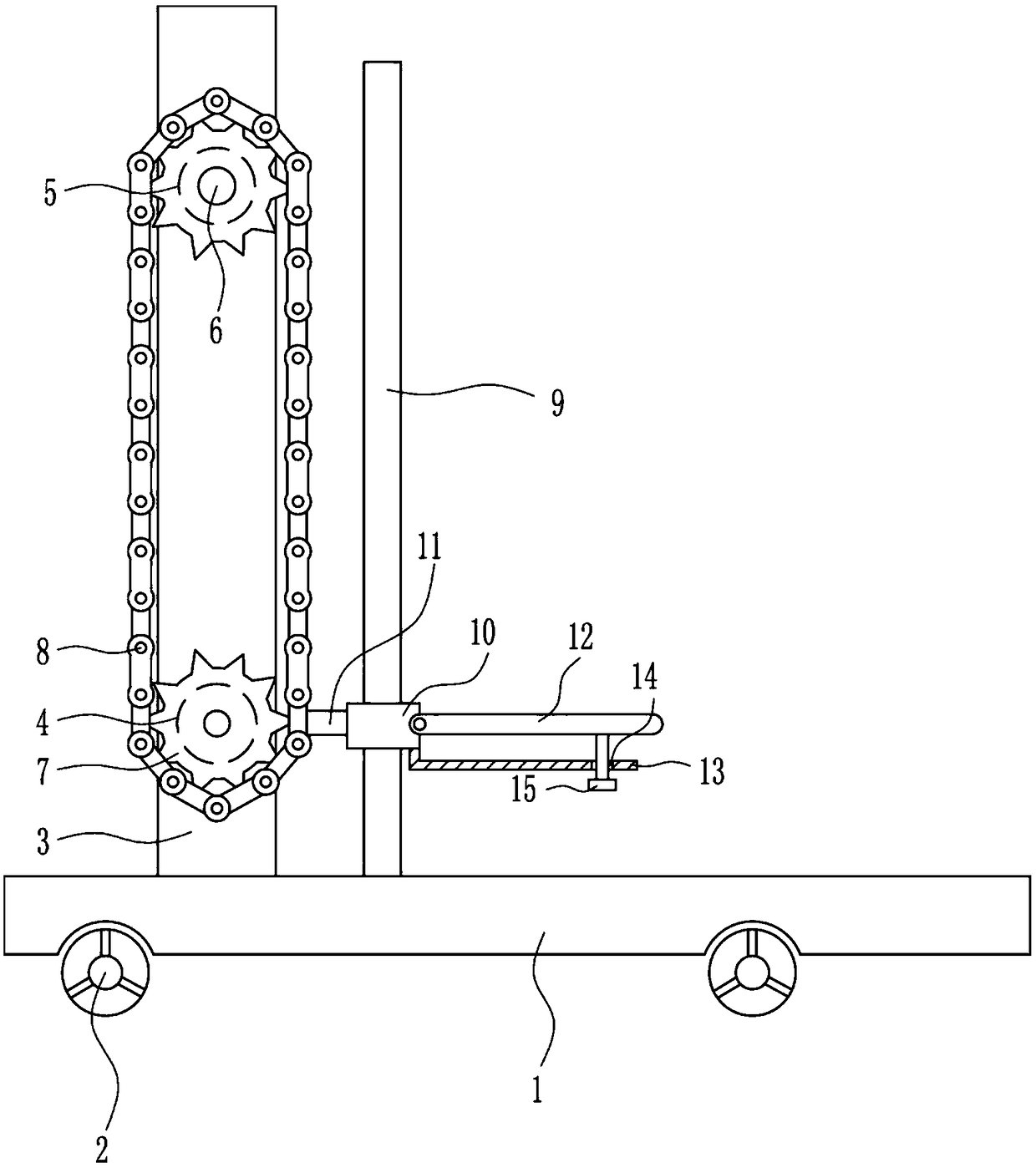
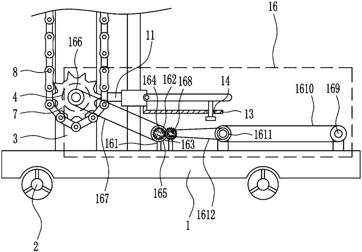
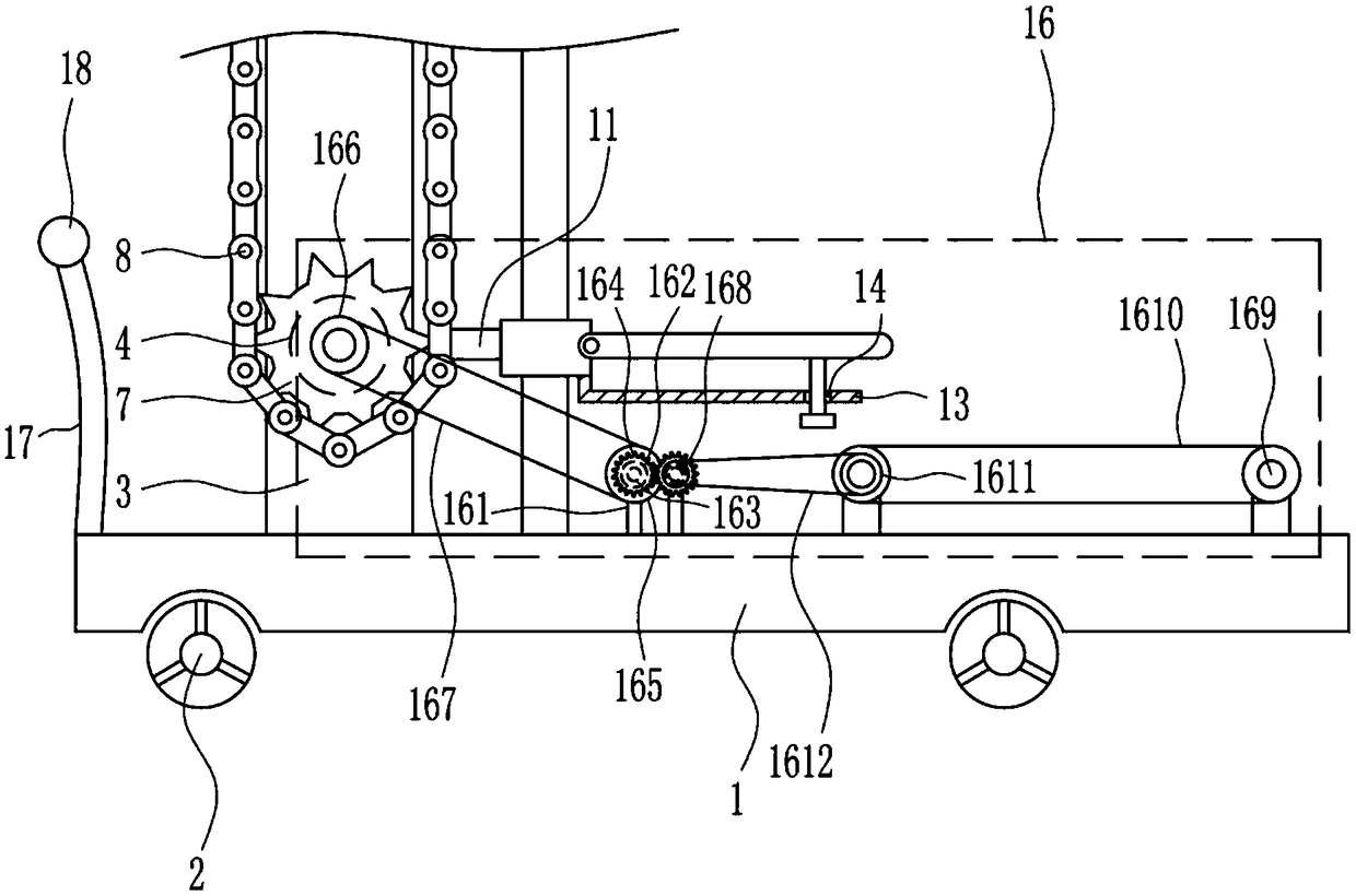
[0024] A mechanical truck unloading device, such as Figure 1-5As shown, it includes base plate 1, wheel 2, mounting plate 3, motor 4, first bearing seat 5, first rotating shaft 6, first gear 7, chain 8, guide rod 9, guide sleeve 10, connecting rod 11, placement Plate 12, L-shaped support plate 13 and bolts 15, the bottom of base plate 1 is equipped with wheels 2, the left side of the top of base plate 1 is provided with mounting plate 3, and the lower part of the front side is provided with motor 4, and the upper part of the front side of mounting plate 3 is provided with a first bearing seat 5. The first bearing seat 5 is provided with a first rotating shaft 6, the front end of the first rotating shaft 6 and the output shaft on the front side of the motor 4 are connected with the first gear 7, and the first gear 7 on the upper and lower sides is wound with a chain 8 , the top left side of the bottom plate 1 is provided with a guide rod 9, the guide rod 9 is on the right side...

Embodiment 2

[0026] A mechanical truck unloading device, such as Figure 1-5 As shown, it includes base plate 1, wheel 2, mounting plate 3, motor 4, first bearing seat 5, first rotating shaft 6, first gear 7, chain 8, guide rod 9, guide sleeve 10, connecting rod 11, placement Plate 12, L-shaped support plate 13 and bolts 15, the bottom of base plate 1 is equipped with wheels 2, the left side of the top of base plate 1 is provided with mounting plate 3, and the lower part of the front side is provided with motor 4, and the upper part of the front side of mounting plate 3 is provided with a first bearing seat 5. The first bearing seat 5 is provided with a first rotating shaft 6, the front end of the first rotating shaft 6 and the output shaft on the front side of the motor 4 are connected with the first gear 7, and the first gear 7 on the upper and lower sides is wound with a chain 8 , the top left side of the bottom plate 1 is provided with a guide rod 9, the guide rod 9 is on the right sid...

Embodiment 3

[0029] A mechanical truck unloading device, such as Figure 1-5 As shown, it includes base plate 1, wheel 2, mounting plate 3, motor 4, first bearing seat 5, first rotating shaft 6, first gear 7, chain 8, guide rod 9, guide sleeve 10, connecting rod 11, placement Plate 12, L-shaped support plate 13 and bolts 15, the bottom of base plate 1 is equipped with wheels 2, the left side of the top of base plate 1 is provided with mounting plate 3, and the lower part of the front side is provided with motor 4, and the upper part of the front side of mounting plate 3 is provided with a first bearing seat 5. The first bearing seat 5 is provided with a first rotating shaft 6, the front end of the first rotating shaft 6 and the output shaft on the front side of the motor 4 are connected with the first gear 7, and the first gear 7 on the upper and lower sides is wound with a chain 8 , the top left side of the bottom plate 1 is provided with a guide rod 9, the guide rod 9 is on the right sid...


PUM


Abstract

The invention relates to a truck unloading device, in particular to a mechanical truck-unloading device. The object of the invention is to provide a mechanical truck-unloading device which can improvethe truck unloading speed and ensure the unloading safety. The invention adopts the following technical scheme: a mechanical truck-unloading device comprises a base plate, wheels, a mounting plate, amotor, a first bearing seat, a first rotating shaft, first gears, a chain, a guide rod, a guide sleeve, a connecting rod, etc., wherein the wheels are mounted at the bottom of the base plate; the mounting plate is arranged on the left side of the top of the base plate; the motor is arranged at the lower part of the front side of the mounting plate; the first bearing seat is arranged at the upperpart of the front side of the mounting plate; the first rotating shaft is arranged in the first bearing seat; and the front end of the first rotating shaft and an output shaft on the front side of themotor are both connected with the first gears. The mechanical truck-unloading device provided by the invention achieves the effects of improving the truck unloading speed and ensuring the unloading safety. Through ascending and descending of a placement plate, the mechanical truck-unloading device can conveniently and quickly unload goods from a truck; and a conveying device can convey goods on aconveying belt to the right side of the base plate, so that a user can unload the goods more conveniently.

Description

technical field [0001] The invention relates to a truck unloading device, in particular to a mechanical truck unloading device. Background technique [0002] With the development of logistics, logistics companies will have a large amount of goods, but the goods are transported by trucks. When transporting to the destination, the goods need to be removed. Because the trucks are high and loaded with many things, so in Unloading will be very slow, and after a long time, people's hands will be sore, which will cause instability in grasping the goods, causing the goods to fall on the ground. At the same time, because the artificial feet are also on the ground, it is so easy to hit the worker's feet. Foot, thus safety accidents occur, when trucks are unloaded at present, it is usually to complete the unloading by multiple workers handing over the goods, which requires a lot of labor. [0003] To sum up, there is a need to develop a mechanical truck unloading device that can speed...

Claims


Application Information

Patent Timeline
Patent Type & Authority Applications(China)
IPC IPC(8): B66F9/24B66F9/20B66F9/075
CPCB66F9/07504B66F9/20B66F9/24
Inventor 万旭芬
Owner JINYIMENG GRP CO LTD
Why Eureka
Try Eureka