Blended yarn impurity removal and conveying mechanism

A conveying mechanism and technology of blended yarns, which are applied in textile and papermaking, fiber processing, fiber cleaning, etc., can solve the problem of combing and removing impurities in blended yarns, yarn breakage of blended yarns, short fibers and impurities in blended yarns Difficulty and other problems, to achieve the effect of reasonable structural design, ensuring efficiency and quality, and ensuring wide width

Inactive Publication Date: 2018-11-13
蔡燕
View PDF0 Cites 6 Cited by
  • Summary
  • Abstract
  • Description
  • Claims
  • Application Information

AI Technical Summary

Problems solved by technology

During the production and processing of blended yarns, the blended yarns need to be conveyed smoothly one by one. During the conveying process of the existing blended yarns, it is difficult to conveniently comb and remove impurities from the blended yarns, resulting in short fibers of the blended yarns. It is difficult to quickly and fully remove impurities and impurities, which affects the quality of blended yarn production and processing in the subsequent process, and it is difficult for the existing blended yarn to be pulled and conveyed smoothly and efficiently during the conveying process, resulting in Partial yarn breakage in the middle affects the normal processing of blended yarn in the subsequent process, which cannot meet the needs of processing and use

Method used


Image

  • Blended yarn impurity removal and conveying mechanism
  • Blended yarn impurity removal and conveying mechanism
  • Blended yarn impurity removal and conveying mechanism

Examples


Embodiment Construction

[0014] In order to further describe the present invention, a specific implementation of a blended yarn impurity removal transmission mechanism will be further described below in conjunction with the accompanying drawings. The following examples are explanations of the present invention and the present invention is not limited to the following examples.

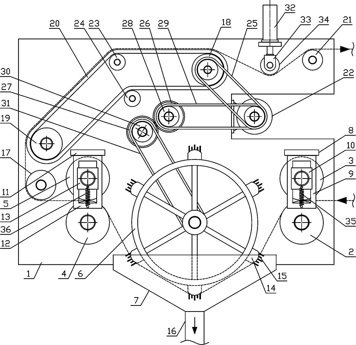
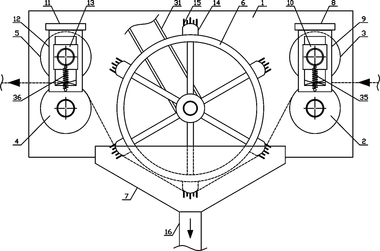
[0015] Such as figure 1 As shown, a blended yarn removal transmission mechanism of the present invention includes a fixed bracket 1, a removal mechanism and a yarn pulling mechanism, and the yarn pulling mechanism and the removal mechanism are fixed horizontally on one side of the fixing bracket 1 from top to bottom. Such as figure 2 As shown, the impurity removal mechanism of the present invention comprises yarn feed roller 2, yarn feed roller 3, yarn outlet roller 4, yarn outlet roller 5, impurity removal drum 6 and dust suction wind cover 7, yarn feed roller 2 and the yarn output rotating roller 4 are horizontally connected...


PUM


Abstract

The invention discloses a blended yarn impurity removal and conveying mechanism, and belongs to the field of textile processing machinery equipment. A yarn pulling mechanism and a impurity removial mechanism are sequentially and fixedly arranged on one side of a fixed support from top to bottom, a impurity removal rotor drum is horizontally and rotatably connected to the fixed support between a yarn inlet roller and the yarn outlet roller, a plurality of impurity removal connecting plates are horizontally and fixedly arranged on the outer side of the impurity removal rotor drum, a plurality ofrows of yarn card wires are uniformly arranged at the outer side of the impurity removal connecting plates along the radial direction of the impurity removal rotor drum; a impurity suction fan coveris horizontally and fixedly arranged on the fixed support on the lower side of the impurity removal rotor drum; a yarn pulling conveying belt is sequentially wound and connected with an upper yarn pulling roller, a belt bearing roller, a lower yarn pulling roller and a belt pressing roller; the yarn bearing roller is horizontally and rotatably connected with the fixed support on one side of the upper yarn pulling roller. The mechanism is reasonable in structural design, and is capable of smoothly and efficiently carding and removing impurities in the conveying process of the blended yarn. Thequality of the blended yarn production and processing is improved and the requirements of production and use are met.

Description

technical field [0001] The invention belongs to the field of textile processing machinery and equipment, in particular to a blended yarn impurity removal transmission mechanism, which is mainly used in the field of continuous production and processing of blended yarns. Background technique [0002] With the development of the production industry and the improvement of people's living standards, people have higher and higher requirements for textile materials. High-end textiles can be woven from high-quality textile materials to meet people's needs. Textile materials refer to fibers and fiber products, which are specifically manifested as fibers, yarns, fabrics and their composites. In modern textiles, the research and development of new textile materials, especially the development and use of nanofibers, has broken through the traditional textile materials. Conceptually, textile materials have become an important component of soft matter materials. As an important textile m...

Claims


Application Information

Patent Timeline
Patent Type & Authority Applications(China)
IPC IPC(8): D02J7/00D01H13/04
CPCD02J7/00D01H13/04
Inventor 蔡燕
Owner 蔡燕
Why Eureka
Try Eureka