Sewing machine
A sewing machine and sewing needle technology, which is applied to sewing machine components, sewing machine needle holders, sewing equipment, etc., can solve the problem of determining the amount of up and down movement of difficult sewing needles.
Active Publication Date: 2018-11-13
JUKI CORP
8 Cites 1 Cited by
AI-Extracted Technical Summary
Problems solved by technology
[0008] Therefore, it is difficult to uniformly determine the amount of vertical mov...
Method used
In addition, in the second adjustment section K2, the control device 100 performs the upper shaft driving of the sewing machine motor 5 until it becomes the upper shaft angle at the beginning of the first adjustment section K1 regardless of the rotation operation of the jog dial 32. Angle control (1), therefore, in trial sewing etc., needle movement can be ...
Abstract
The invention provides a sewing machine in which proper vertical movement of a sewing needle is performed by using an inching rotary disc. The sewing machine comprises a sewing needle vertical movement mechanism which passes by an upper shaft via a sewing machine motor to make a needle bar holding the sewing needle to move vertically, and a control device which controls the rotation movement of the upper shaft realized by the sewing machine motor. The sewing machine is provided with an inching rotary disc which enables drive of the sewing machine motor through rotation operation so as to adjust the upper shaft angle of the upper shaft. The control device performs control to set part of the range of the upper shaft angle to be a first adjusting interval in which the drive of the sewing machine motor is enabled with a stipulated resolution relative to the rotation operation of the inching rotary disc and set the other part of the range of the angle except for the first adjusting intervalor all the angle range to be a second adjusting interval in which the drive of the sewing machine motor is enabled through motion different from that in the first adjusting interval.
Application Domain
Programme-controlled sewing machinesNeedle bars
Technology Topic
Sewing needleEngineering +1
Image
Examples
- Experimental program(1)
Example Embodiment
[0058] [Sewing Machine Outline]
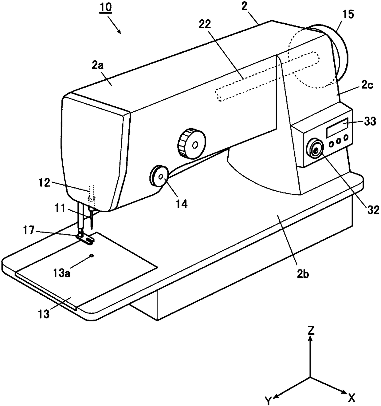
[0059] Hereinafter, embodiments of the present invention will be described in detail based on the drawings. figure 1 It is a perspective view which shows the whole structure of the sewing machine 10 which is this embodiment. In addition, in the following description, the direction horizontal and parallel to the longitudinal direction of the sewing machine arm portion 2a described later is referred to as the Y-axis direction (left-right direction), and the direction horizontal and perpendicular to the Y-axis direction is referred to as the X-axis. As for the direction (front-back direction), the vertical up-down direction is defined as the Z-axis direction (up-down direction).
[0060] like figure 1 As shown, the sewing machine 10 is a so-called lockstitch sewing machine, which has: a sewing machine frame 2, which supports the overall structure; a sewing needle up and down movement mechanism (illustration omitted), which makes the needle bar 12 holding the sewing needle 11 move up and down; The sewing machine motor 5 serves as a driving source for vertical movement of the needle bar 12 , and the control device 100 controls the operation of the sewing machine motor 5 .
[0061] also, figure 1 The reference numeral 14 in is the thread regulator that applies thread tension to the upper thread. In addition, of course, there are a thread take-up mechanism, a kettle mechanism, a cloth feeding mechanism, etc. that are usually mounted on a lockstitch sewing machine, but these mechanisms are the same as conventionally known structures, so descriptions are omitted.
[0062] [Sewing rack]
[0063] The sewing machine frame 2 has a substantially U-shaped outer shape when viewed from the front. This sewing machine frame 2 has: a sewing machine arm portion 2a, which constitutes an upper portion of the sewing machine frame 2, and extends in the left-right direction; a sewing machine base portion 2b, which constitutes a lower portion of the sewing machine frame 2, and extends in the left-right direction; and a longitudinal body portion 2c, which The sewing machine arm part 2a and the sewing machine base part 2b are connected.
[0064] [Sewing needle up and down movement mechanism]
[0065] A sewing needle up and down movement mechanism is incorporated in the sewing machine arm portion 2a. This sewing needle up and down movement mechanism has: sewing machine motor 5 (referring to figure 2 ), which becomes the drive source; the upper shaft 22, which is rotationally driven by the sewing machine motor 5; the needle bar 12, which holds the sewing needle 11 at the lower end and is supported on the sewing machine arm 2a so as to be movable up and down; and the crank mechanism (illustration omitted), which converts the rotation of the upper shaft 22 into a reciprocating motion along the Z-axis direction.
[0066] In addition, one end of the upper shaft 22 is fixedly equipped with a rotating pulley 15 that can be manually operated from the outside of the sewing machine frame 2 .
[0067]Below the needle bar 12 and on the upper portion of the sewing machine base portion 2b, a needle plate 13 having a needle hole 13a into which the sewing needle 11 is inserted is formed. Furthermore, a tank (not shown) is disposed below the needle plate 13 .
[0068] In addition, the cloth presser 17 is adjacent to the needle bar 12 and supported by the sewing machine arm 2a. The material presser foot 17 is supported so as to be able to move up and down, and presses the clothing as a sewing object on the needle plate 13 from above when it is lowered, and releases the clothing when it is raised.
[0069] [Sewing machine control system]
[0070] figure 2 It is a block diagram showing the control system of the sewing machine 10 . as it should figure 2 As shown, the control device 100 of the sewing machine 10 has: a CPU 101, which executes control programs for each part of the sewing machine; a job memory 102, which becomes a work area for program processing; a data memory 103, which sets various controls Data and execution programs are stored; and a counter 104 counts pulse signals from the outside.
[0071] In addition, the sewing machine motor 5 is connected to the control device 100 via a drive circuit 5a.
[0072] In addition, the control device 100 is connected via unillustrated interfaces: an encoder 51 for detecting the output shaft angle of the sewing machine motor 5; and an operation panel 33 for controlling the operation of sewing by the operator. Related various inputs; the operating pedal 34 as the operating part, which is used to artificially input the instruction of sewing start to the control device 100; And the upper shaft angle of the upper shaft 22 is adjusted.
[0073] The encoder 51 detects the shaft angle of the output shaft of the sewing machine motor 5, and inputs a pulse signal to the control device 100 according to the amount of change in the shaft angle.
[0074] In the control device 100, the counter 104 counts the pulse signal from the encoder 51, and calculates the current upper shaft angle based on the count value.
[0075] The jog dial 32 can rotate clockwise and counterclockwise without restriction, and input pulses to the control device 100 proportional to the rotation angle. In addition, the jog dial 32 is internally provided with a latch structure so as to generate a latching feeling of 30 clicks in a range of 360° of one rotation. That is, when the operator rotates the jog dial 32 , he/she can get a locked feeling once every 12° of rotation.
[0076] In addition, if the control device 100 rotates the jog dial 32 clockwise (set as positive rotation), the sewing machine motor 5 makes the upper shaft 22 rotate positively (consistent with the rotation direction during sewing), and if the jog dial 32 When the sewing machine motor 5 rotates counterclockwise (referred to as reverse rotation), the upper shaft 22 rotates reversely.
[0077] [Upper shaft angle control corresponding to the rotation operation of the jog dial (1)]
[0078] The control device 100 selectively executes the upper shaft angle control (1) and (2) corresponding to the rotation operation of the jog dial 32 with respect to the sewing machine motor 5 that rotates the upper shaft 22 . kind of control. The selection of the upper shaft angle control (1) and (2) can be performed by manual selection input from the operation panel 33 . Thus, the operation panel 33 functions as a selection unit.
[0079] First, based on image 3 , the upper shaft angle control (1) corresponding to the rotation operation of the jog dial will be described.
[0080] like image 3 As shown, the control device 100 divides the range of one rotation (360°) of the upper axis angle into two parts, the first adjustment interval K1 and the second adjustment interval K2, which belong to the first adjustment interval K1 and the second adjustment interval K2 according to the current upper axis angle. Which one of the section K2 is adjusted, and which one of the normal rotation and the reverse rotation of the jog dial 32 is operated, performs different control on the sewing machine motor 5 .
[0081] In addition, in the present embodiment, the first adjustment zone K1 is defined as the range from the upper stop position until immediately before reaching the bottom dead center of the needle bar, and the second adjustment zone K2 is defined as the range from the bottom dead center of the needle bar to just before reaching the bottom dead center of the needle bar. The range before the upper stop position.
[0082] The upper stop position is a position where the needle bar 11 descends halfway through the top dead center of the needle bar which is the highest position, and is a position where the needle 11 is located above the needle plate 13 . In the case where the top dead center of the needle bar is set to 0°, for example, the top stop position is set to 70°. Also, set the bottom dead center of the needle bar to 180°. In the above example, the upper axis angle of the first adjustment zone K1 is greater than or equal to 70° and less than 180°, and the upper axis angle of the second adjustment zone K2 is greater than or equal to 180° and less than 70°. In addition, the first adjustment section K1 may be a range of 180° including the bottom dead center of the needle bar, and the second adjustment section K2 may be a range of 180° not including the bottom dead center of the needle bar.
[0083] When positive rotation is input to the jog dial 32 and the current upper shaft angle is within the range of the first adjustment interval K1, the control device 100 determines the first adjustment interval K1 with respect to the rotation operation of the jog dial 32 . The predetermined resolution of the sewing machine motor 5 is driven to rotate the upper shaft 22 forward.
[0084] Also, the resolution represents the ratio of the rotation angle of the sewing machine motor 5 to the rotation angle of the jog dial 32 . In the case of low resolution, the ratio of the rotation angle of the sewing machine motor 5 to the rotation angle of the jog dial 32 is large, and in the case of high resolution, the ratio of the rotation angle of the sewing machine motor 5 to the rotation angle of the jog dial 32 is large. The ratio is small.
[0085] The first adjustment section K1 is a section that requires fine adjustment of the height of the tip of the sewing needle 11, such as adjustment work such as alignment of the needle entry position. In this first adjustment section K1, the sewing machine motor 5 drives.
[0086] In addition, the resolution at which the upper shaft 22 makes one rotation corresponding to two rotations of the jog dial 32 is referred to as an average resolution, and a resolution higher than the average resolution is referred to as a high resolution. The resolution with low resolution is set to low resolution.
[0087] In addition, it is preferable that the resolution of the above-mentioned first adjustment section K1 can be set to an arbitrary value through the operation panel 33 . In this case, the operation panel 33 functions as a "setting unit for arbitrarily setting the upper axis angle range of the first adjustment section".
[0088] In addition, when the positive rotation is input to the jog dial 32 and the current upper shaft angle is within the range of the second adjustment section K2, the control device 100 performs the following control, that is, the amount of rotation operation of the jog dial 32 Regardless, the sewing machine motor 5 is driven so that the upper shaft 22 rotates normally until it reaches the upper shaft angle at the upper stop position, which is the start angle of the first adjustment section K1.
[0089] The second adjustment interval K2 is an interval other than the first adjustment interval K1 suitable for adjustment work. This section is assigned, for example, as a section when the needle is lifted up from the needle drop in order to perform trial sewing or the like. That is, if the upper shaft angle enters the second adjustment zone K2, the sewing needle 11 will automatically move up and down until the upper stop position, and the needle can be moved without the operator having to apply the workload of rotating the jog dial 32. .
[0090] In addition, when the reverse rotation of the jog dial 32 is input, the control device 100 controls the rotation of the jog dial 32 irrespective of which of the first adjustment zone K1 and the second adjustment zone K2 the current upper axis angle belongs to. The sewing machine motor 5 is driven so that the upper shaft 22 rotates in the reverse direction at a predetermined resolution determined by the rotation operation of the reverse rotation.
[0091] In addition, the resolution of the above-mentioned reverse rotation may be a high resolution, a low resolution, or an average resolution, and may be an arbitrary value that can be set on the operation panel 33 .
[0092] In addition, the resolution of the reverse rotation of the jog dial 32 can be changed depending on which range the upper shaft angle is in between the first adjustment interval K1 and the second adjustment interval K2.
[0093] [Upper shaft angle control corresponding to the rotation operation of the jog dial (2)]
[0094] Next, based on Figure 4 , the upper shaft angle control (2) corresponding to the rotation operation of the jog dial will be described.
[0095] In addition, in this embodiment, the first adjustment zone K1 is set from the position where the sewing needle 11 descends halfway through the top dead center and just before piercing the object to be sewn until the sewing needle 11 is lower than the needle plate. The lower position and the range before the bottom dead center set the range other than the first adjustment area as the second adjustment area K2.
[0096] When the top dead center of the needle bar is set at 0°, the upper shaft angle at the position before the needle penetrates the sewing object is set at, for example, 80°. In addition, the upper axis angle at the position where the needle is located below the needle plate is set to, for example, 120°.
[0097] Therefore, in the above example, the upper axis angle of the first adjustment zone K1 is greater than or equal to 80° and less than 120°, and the upper axis angle of the second adjustment zone K2 is greater than or equal to 120° and less than 80°.
[0098] like Figure 4 As shown, when the control device 100 executes the upper shaft angle control (2), when positive rotation is input to the jog dial 32 and the current upper shaft angle is within the range of the first adjustment interval K1, relative to the point The rotary operation of the rotary dial 32 drives the sewing machine motor 5 with a predetermined resolution determined for the first adjustment zone K1, and causes the upper shaft 22 to rotate normally. That is, when the positive rotation is input to the jog dial 32 and the upper shaft 22 is in the first adjustment section K1, the same control as the upper shaft angle control (1) is executed.
[0099] In addition, the resolution of the first adjustment section K1 in the upper axis angle control (2) can be set the same as that of the upper axis angle control (1), or can be set independently of the upper axis angle control (1). In addition, an arbitrary numerical value independent of the upper shaft angle control (1) may be set via the operation panel 33 .
[0100] In addition, the control device 100 performs control such that, when positive rotation is input to the jog dial 32 and the current upper shaft angle is within the range of the second adjustment section K2, The sewing machine motor 5 is driven with a lower resolution than the first adjustment interval K1.
[0101] As described above, the second adjustment section K2 is a section other than the first adjustment section K1 suitable for the adjustment work, and is allocated when the needle is lifted from the needle drop for performing trial sewing or the like. Therefore, when the upper shaft 22 enters the second adjustment zone K2, the sewing machine motor 5 is driven with a low resolution to rotate the upper shaft 22, thereby enabling rapid needle movement.
[0102] Figure 5 It is a line diagram showing the resolution of the first adjustment interval K1 and the second adjustment interval K2 in the upper axis angle control (2), the solid line L1 indicates the resolution in the upper axis angle control (2), and the dotted line L2 indicates the constant Average resolution (comparative example).
[0103]In the upper shaft angle control (2), it is set such that if the jog dial 32 is rotated twice (60 times of locking), the resolution changes halfway, but in total, the upper shaft 22 makes one rotation ( 360°). As shown in the figure, when the angle of the upper axis is within the range of the first adjustment interval K1 (80°-120°), when positive rotation is input to the jog dial 32 , the locking of the jog dial 32 will be performed once. On the other hand, the upper shaft 22 is rotated by 2° at high resolution, and the sewing machine motor 5 is driven to rotate the upper shaft 22 .
[0104] In addition, when the angle of the upper shaft is within the range of the second adjustment interval K2 (120° to 80°), when positive rotation is input to the jog dial 32 , the upper shaft 22 is locked by one click of the jog dial 32 . Rotating the low resolution of 8°, the sewing machine motor 5 is driven to rotate the upper shaft 22 .
[0105] In addition, in the comparative example, the sewing machine motor 5 was rotated at an average resolution of 6 degrees of rotation of the upper shaft 22 corresponding to one click over the entire range of two rotations of the jog dial 32 (60 clicks). Drive in the range of 0 to 360°.
[0106] In addition, when reverse rotation is input to the jog dial 32, the control device 100 controls the sewing machine at a predetermined resolution determined for the reverse rotation operation of the jog dial 32 regardless of the current upper shaft angle. The motor 5 is driven in reverse rotation.
[0107] In this case, the resolution of the reverse rotation may be either a high resolution or a low resolution, and may be set to an arbitrary value through the operation panel 33 .
[0108] In addition, the resolution of the reverse rotation of the jog dial 32 may be changed depending on which range the upper shaft angle is in between the first adjustment section K1 and the second adjustment section K2.
[0109] [Adjustment action by upper shaft angle control (1)]
[0110] based on Image 6 The flow chart of FIG. 2 describes the adjustment operation realized by the upper shaft angle control (1) of the control device 100.
[0111] If the upper shaft angle control (1) is selected through the operation panel 33, the control device 100 becomes the monitoring state of the rotation operation of the jog dial 32 except during the sewing operation performed by stepping in the operation pedal 34. , it is judged whether the input of the normal rotation of the jog dial 32 exists (step S1).
[0112] And if the positive rotation input of the jog dial 32 is detected (step S1: YES), the control device 100 calculates the current upper shaft angle with reference to the output of the encoder 51 of the sewing machine motor 5, and determines whether the upper shaft angle is It is judged that it is in the first adjustment interval K1 (step S3).
[0113] As a result, when the upper shaft angle is within the first adjustment interval K1 (step S3: YES), with respect to the rotation operation of the jog dial 32, at the predetermined high resolution determined for the first adjustment interval K1, The sewing machine motor 5 is driven to rotate normally (step S5), and the process ends. In addition, when the upper axis angle is not in the first adjustment interval K1 but in the second adjustment interval K2 (step S3: NO), regardless of the amount of rotational operation of the jog dial 32, until the first adjustment interval K1 is reached. The sewing machine motor 5 is driven in a normal rotation mode until the start angle of , that is, the upper shaft angle of the upper stop position (step S7), and the process ends.
[0114] In addition, when the control device 100 does not detect the input of the positive rotation of the jog dial 32 in the determination of step S1 (step S1: NO), it determines whether the input of the reverse rotation of the jog dial 32 is present (step S1: NO). S9).
[0115] And if the input of the reverse rotation of the jog dial 32 is detected (step S9: YES), the control device 100 drives the sewing machine motor 5 at a predetermined resolution determined for the reverse rotation of the jog dial 32. Drive in reverse rotation (step S11), and end the process.
[0116] In addition, when the control apparatus 100 does not detect the reverse rotation input of the jog dial 32 in the determination of step S9 (step S9: NO), it considers that the jog dial 32 is not rotated at all, and ends a process.
[0117] Note that the upper shaft angle control (1) is repeatedly executed at a predetermined cycle while the operation pedal 34 is not depressed.
[0118] [Adjustment action by upper shaft angle control (2)]
[0119] based on Figure 7 The flow chart of FIG. 2 describes the adjustment operation realized by the upper shaft angle control (2) of the control device 100 .
[0120] If the upper shaft angle control (2) is selected through the operation panel 33, the control device 100 becomes the monitoring state of the rotation operation of the jog dial 32 except during the sewing operation performed by stepping in the operation pedal 34. , it is determined whether or not the input of the normal rotation of the jog dial 32 is present (step S21).
[0121] And if the positive rotation input of the jog dial 32 is detected (step S21: YES), the control device 100 refers to the output of the encoder 51 of the sewing machine motor 5 to calculate the current upper shaft angle, and determines whether the upper shaft angle is It is determined that it is in the first adjustment interval K1 (step S23).
[0122] As a result, when the upper axis angle is within the first adjustment interval K1 (step S23: YES), with respect to the rotation operation of the jog dial 32, at the predetermined high resolution determined for the first adjustment interval K1, The sewing machine motor 5 is driven to rotate normally (step S25), and the process ends.
[0123] In addition, when the upper axis angle is not in the first adjustment interval K1 but in the second adjustment interval K2 (step S23: NO), the rotation operation of the jog dial 32 is determined for the second adjustment interval K2. The predetermined low resolution is set, the sewing machine motor 5 is driven to rotate forward (step S27), and the process ends.
[0124] In addition, when the control device 100 does not detect the input of the positive rotation of the jog dial 32 in the determination of step S1 (step S21: NO), it determines whether the input of the reverse rotation of the jog dial 32 is present (step S21: NO). S29).
[0125] And if the input of the reverse rotation of the jog dial 32 is detected (step S29: YES), the control device 100 drives the sewing machine motor 5 at a predetermined resolution determined for the reverse rotation of the jog dial 32. Drive in reverse rotation (step S31), and end the process.
[0126] Moreover, when the control apparatus 100 does not detect the reverse rotation input of the jog dial 32 in the determination of step S29 (step S29: NO), it considers that the jog dial 32 is not rotated at all, and ends a process.
[0127] In addition, this upper shaft angle control (2) is repeatedly executed at a predetermined cycle even when the operation pedal 34 is not depressed.
[0128] [Technical Effects of Embodiments]
[0129] In the above-mentioned sewing machine 10, the control device 100 performs control such that a part of the angular range of the upper shaft 22 is set as the first one that drives the sewing machine motor 5 with a predetermined resolution in response to the rotation operation of the jog dial 32. In the adjustment section K1, the angular range other than the first adjustment section K1 is set as the second adjustment section K2 in which the sewing machine motor 5 is driven by a different operation from the first adjustment section K1.
[0130] Therefore, when the jog dial 32 is used for different purposes such as adjustment work accompanied by vertical movement of the sewing needle 11, trial sewing, etc., it is also possible to drive the sewing machine motor 5 suitable for each application. Jog the turntable 32 to perform appropriate vertical movement of the sewing needle 11 .
[0131] In addition, the control device 100 performs the upper shaft angle control in which the sewing machine motor 5 is driven until the upper shaft angle at the beginning of the first adjustment section K1 is reached regardless of the rotation operation of the jog dial 32 in the second adjustment section K2 ( 1) Therefore, during trial sewing or the like, needle movement can be performed smoothly and quickly, and workability can be improved. In addition, the upper shaft angle control (1) is to automatically rotate the upper shaft 22 until the upper shaft angle reaches the upper stop position when it enters the second adjustment zone K2. The movable dial 32 continues to rotate, and it is possible to reduce the burden of operation.
[0132] In addition, the control device 100 performs the upper shaft angle control (2) in which the sewing machine motor 5 is driven with a resolution lower than that in the first adjustment interval K1 in response to the rotational operation of the jog dial 32 in the second adjustment interval K2. , In this case, the needle movement can be smoothly and quickly performed during trial sewing or the like, and the workability can be improved. In addition, the upper shaft angle control (2) can arbitrarily stop the sewing machine motor 5 regardless of the adjustment section, so that trial sewing can be performed while checking the formation state of stitches and the like.
[0133] In addition, when the control device 100 is configured to have the operation panel 33 as a setting unit for arbitrarily setting the upper shaft angle range of the first adjustment section K1 for the upper shaft angle controls (1) and (2), it is possible to By realizing the optimization of the section in which the adjustment work accompanying the vertical movement of the sewing needle 11 is performed, the optimization of the adjustment work and the speed-up of trial sewing can be performed in a well-balanced manner.
[0134] [other]
[0135] The upper axis angle ranges of the first adjustment interval K1 and the second adjustment interval K2 in the aforementioned upper axis angle control (1) and (2) can also be changed arbitrarily through the operation panel 33, but regarding the first adjustment interval K1 is preferably set to a range in which the sewing needle 11 descends midway through the top dead center position of the needle bar at the highest position, and at least includes the angle at which the sewing needle 11 penetrates into the object to be sewn or the needle plate 13. within the range. That is, it is preferable that the first adjustment zone K1 includes the range of the upper axis angle of 80° to 100°. This is because the front and rear of this range are often used for adjustment operations involving the vertical movement of the sewing needle 11 .
[0136] In addition, it is not limited to the above-mentioned range, and the first adjustment zone K1 may include a range of 180° to 200° of an upper shaft angle passing through the bottom dead center of the needle bar. The reason for this is that the range of the upper axis angle of 190° is the upper axis angle above the passage line from the tip of the kettle to the needle 11, and is often used for adjusting the kettle alignment.
[0137] In addition, the first adjustment section may be arbitrarily set within a range including either or both of the above-mentioned angle at which the sewing needle 11 penetrates into the object to be sewn or the needle plate 13 and the bottom dead center of the needle bar. The range of the upper axis angle of K1.
[0138] In addition, the angle range of the upper axis 22 is divided into two parts, the first adjustment interval K1 and the second adjustment interval K2, but it can also be divided into more adjustment intervals, one of which is set as the first adjustment interval K1, and the other One is set as the second adjustment interval K2. In addition, in this case, it is preferable to rotate the jog dial 32 with respect to the sections that do not belong to any one of the first adjustment section K1 and the second adjustment section K2 in the same manner as the first adjustment section K1 and the second adjustment section K2. The inherent resolutions of the different intervals K2 are adjusted to drive the sewing machine motor 5 .
[0139] In addition, the upper shaft angle control (1) and (2) can be applied to all sewing machines regardless of the model.
[0140] In addition, the installation position of the jog dial 32 may be installed at any position as long as it is within the reach of the operator. The installation place may be not only the sewing machine frame 2 but also a table on which the sewing machine 10 is installed. In addition, a remote control type that is separate from the sewing machine 10 may also be used.
PUM


Description & Claims & Application Information
We can also present the details of the Description, Claims and Application information to help users get a comprehensive understanding of the technical details of the patent, such as background art, summary of invention, brief description of drawings, description of embodiments, and other original content. On the other hand, users can also determine the specific scope of protection of the technology through the list of claims; as well as understand the changes in the life cycle of the technology with the presentation of the patent timeline. Login to view more.