Road protective fence for municipal engineering

A guardrail and engineering technology, applied in the direction of roads, roads, road safety devices, etc., can solve problems such as car accidents, secondary traffic accidents of guardrails, increased maintenance, etc., and achieve a small degree of damage, good use effect, and strong applicability Effect

Inactive Publication Date: 2018-11-13
芜湖等莱智能科技有限公司
View PDF13 Cites 13 Cited by
  • Summary
  • Abstract
  • Description
  • Claims
  • Application Information

AI Technical Summary

Problems solved by technology

[0002] Guardrails are generally installed in the middle of the existing roads to separate two-way lanes, but people often find that the guardrails are seriously damaged. This is because the vehicle directly hits the guardrails in an accident. Because the guardrails directly bear the impact, Therefore, in many cases, when the impact force of the vehicle is too large, it will rush into the opposite lane, causing the oncoming car to directly hit it, causing a more serious car accident. If all the guardrails are made of high-strength metal materials, the cost will be very huge , if ordinary materials are used, it is prone to secondary traffic accidents caused by vehicles crashing into guardrails
The guardrails in the prior art are generally welded and fixedly connected, so that when the guardrail is hit, the whole guardrail will be affected by the impact and deformed. This is due to the disadvantages of the welded one-piece structure, which makes maintenance difficult. increase, cost increase
Moreover, after a long time of use, the welded guardrail is easy to crack at the welded joint, which affects the service life of the entire guardrail
When the guardrail is hit, there is no buffer, and the risk factor is high

Method used


Image

  • Road protective fence for municipal engineering
  • Road protective fence for municipal engineering

Examples


Embodiment Construction

[0017] The following will clearly and completely describe the technical solutions in the embodiments of the present invention with reference to the accompanying drawings in the embodiments of the present invention. Obviously, the described embodiments are only some, not all, embodiments of the present invention. Based on the embodiments of the present invention, all other embodiments obtained by persons of ordinary skill in the art without making creative efforts belong to the protection scope of the present invention.

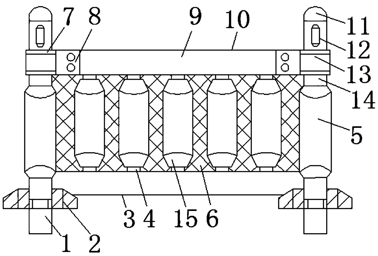
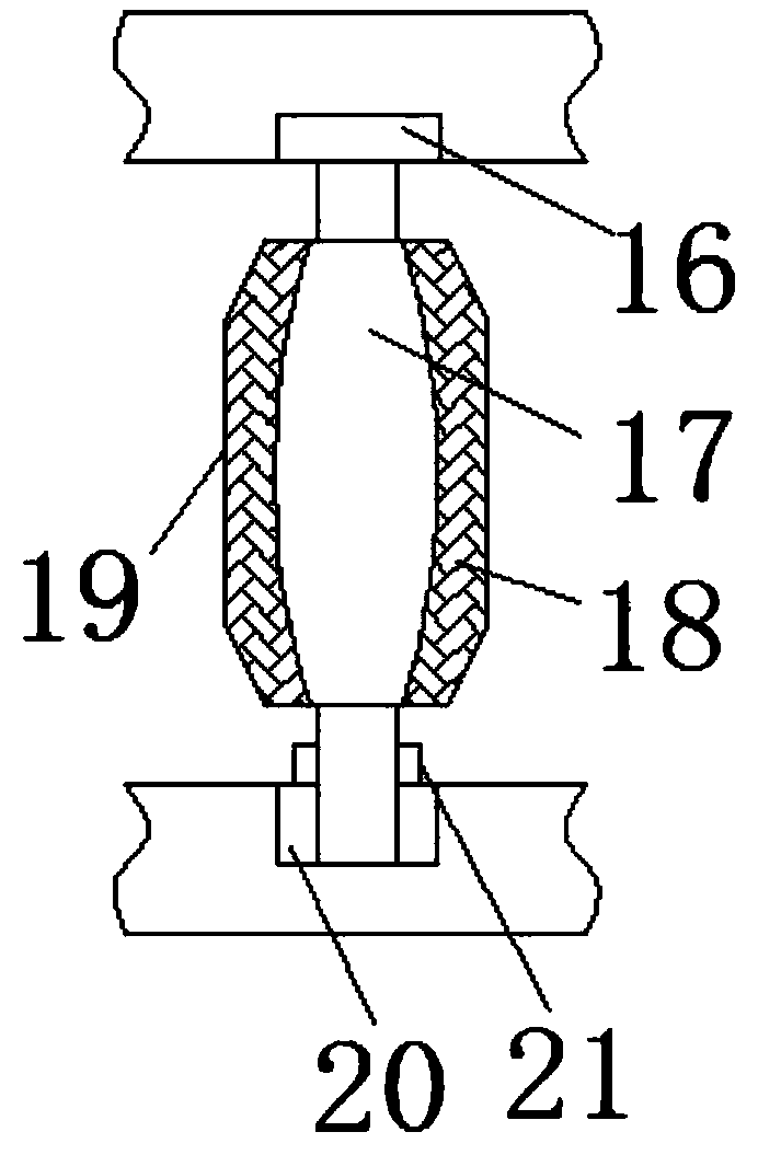
[0018] see Figure 1-2 , the present invention provides a technical solution: a road guardrail for municipal engineering, comprising a lower beam 3, one end of the lower beam 3 is connected to the first column 1, and the other end of the lower beam 3 is fixed to the second column 14, The second column 14 is connected to the inner side of the top of the first column 1 through an upper beam 9, and the two ends of the upper beam 9 are provided with a connecting p...


PUM


Abstract

The invention discloses a road protective fence for municipal engineering. The road protective fence comprises a lower crossbeam. One end of the lower crossbeam is connected with first vertical columns. The other end of the lower crossbeam is fixed to second vertical columns. The inner sides of the top ends of the second vertical columns and the first vertical columns are connected through an upper crossbeam. Connecting pieces are arranged at the two ends of the upper crossbeam. Sliding sleeves are arranged at one ends of the connecting pieces and arranged at the peripheries of bosses in a sleeving mode. The bosses are integrally formed at the tops of the first vertical columns and the second vertical columns. The top ends of the bosses are wrapped with rubber sleeves. The peripheries of the middles of the first vertical columns and the second vertical columns are movably connected with first rotating barrels. An anti-collision net is fixed between the upper crossbeam and the lower crossbeam. According to the road protective fence, the first rotating barrels and second rotating barrels are arranged, thus when a vehicle accidentally hits against the protective fence, a vehicle bodymoves after making contact with the first rotating barrels and the second rotating barrels, part of impact force is dispersed, rigid collision with hard objects is avoided, the damage extent is small,and safety is high.

Description

technical field [0001] The invention relates to the technical field of municipal construction equipment, in particular to a road guardrail for municipal engineering. Background technique [0002] Guardrails are generally installed in the middle of the existing roads to separate two-way lanes, but people often find that the guardrails are seriously damaged. This is because the vehicle directly hits the guardrails in an accident. Because the guardrails directly bear the impact, Therefore, in many cases, when the impact force of the vehicle is too large, it will rush into the opposite lane, causing the oncoming car to directly hit it, causing a more serious car accident. If all the guardrails are made of high-strength metal materials, the cost will be very huge , if ordinary materials are used, it is prone to secondary traffic accidents caused by vehicles crashing into the guardrail. The guardrails in the prior art are generally welded and fixedly connected, so that when the g...

Claims


Application Information

Patent Timeline
Patent Type & Authority Applications(China)
IPC IPC(8): E01F15/02E01F15/14
CPCE01F15/02E01F15/146
Inventor 袁先念
Owner 芜湖等莱智能科技有限公司
Why Eureka
Try Eureka