Pump body assembly, fluid machinery and heat exchange equipment

A component and pump body technology, applied in mechanical equipment, liquid variable capacity machinery, pump components, etc., can solve problems such as affecting the working efficiency of pump body components and easy eccentric rotation of the piston sleeve.

Pending Publication Date: 2018-11-13
GREE ELECTRIC APPLIANCES INC
View PDF6 Cites 4 Cited by
  • Summary
  • Abstract
  • Description
  • Claims
  • Application Information

AI Technical Summary

Problems solved by technology

[0003] The main purpose of the present invention is to provide a pump body assembly, fluid machinery and heat exchange equipment to solve the problem in

Method used


Image

  • Pump body assembly, fluid machinery and heat exchange equipment
  • Pump body assembly, fluid machinery and heat exchange equipment
  • Pump body assembly, fluid machinery and heat exchange equipment

Examples


Embodiment 1

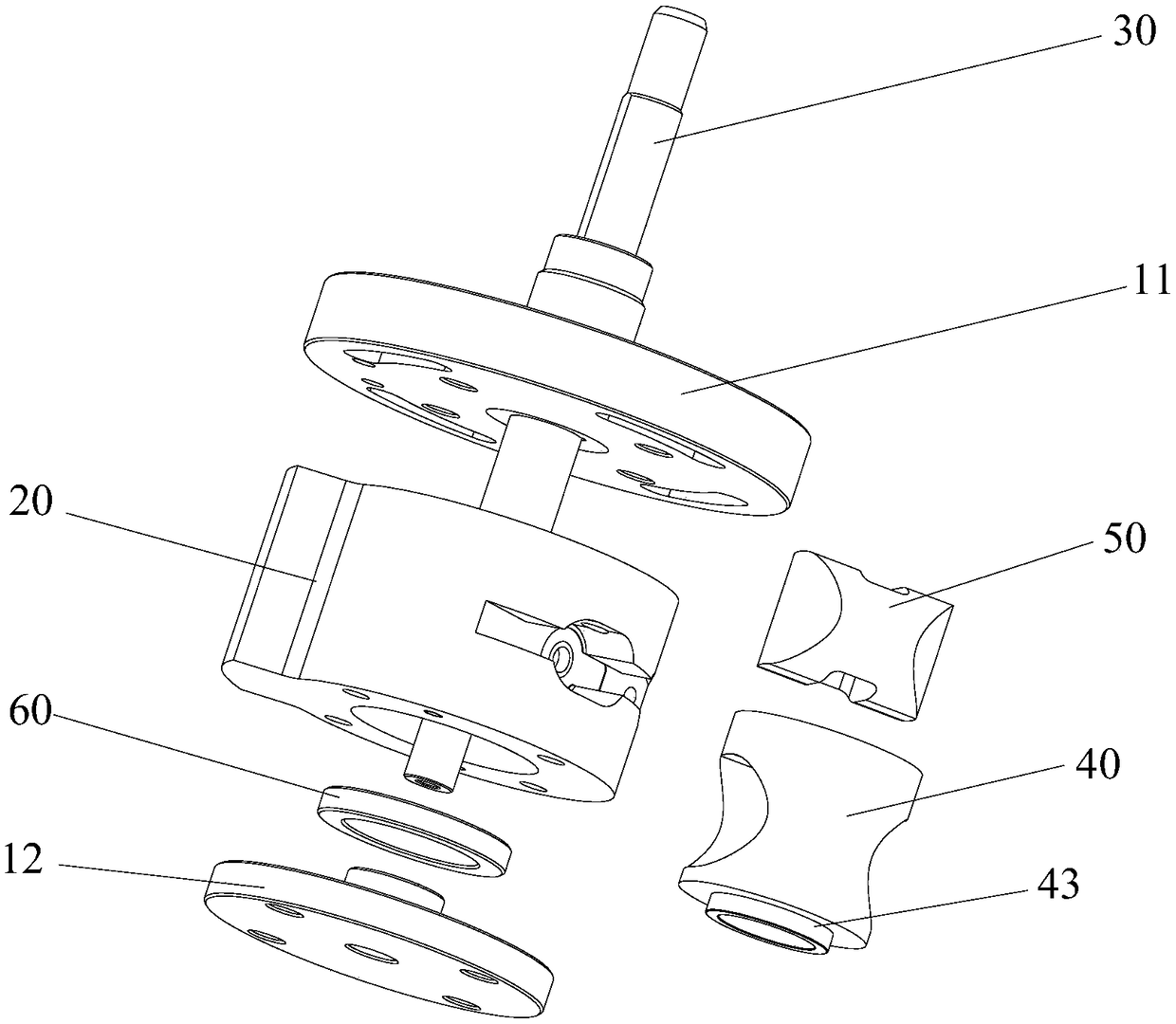
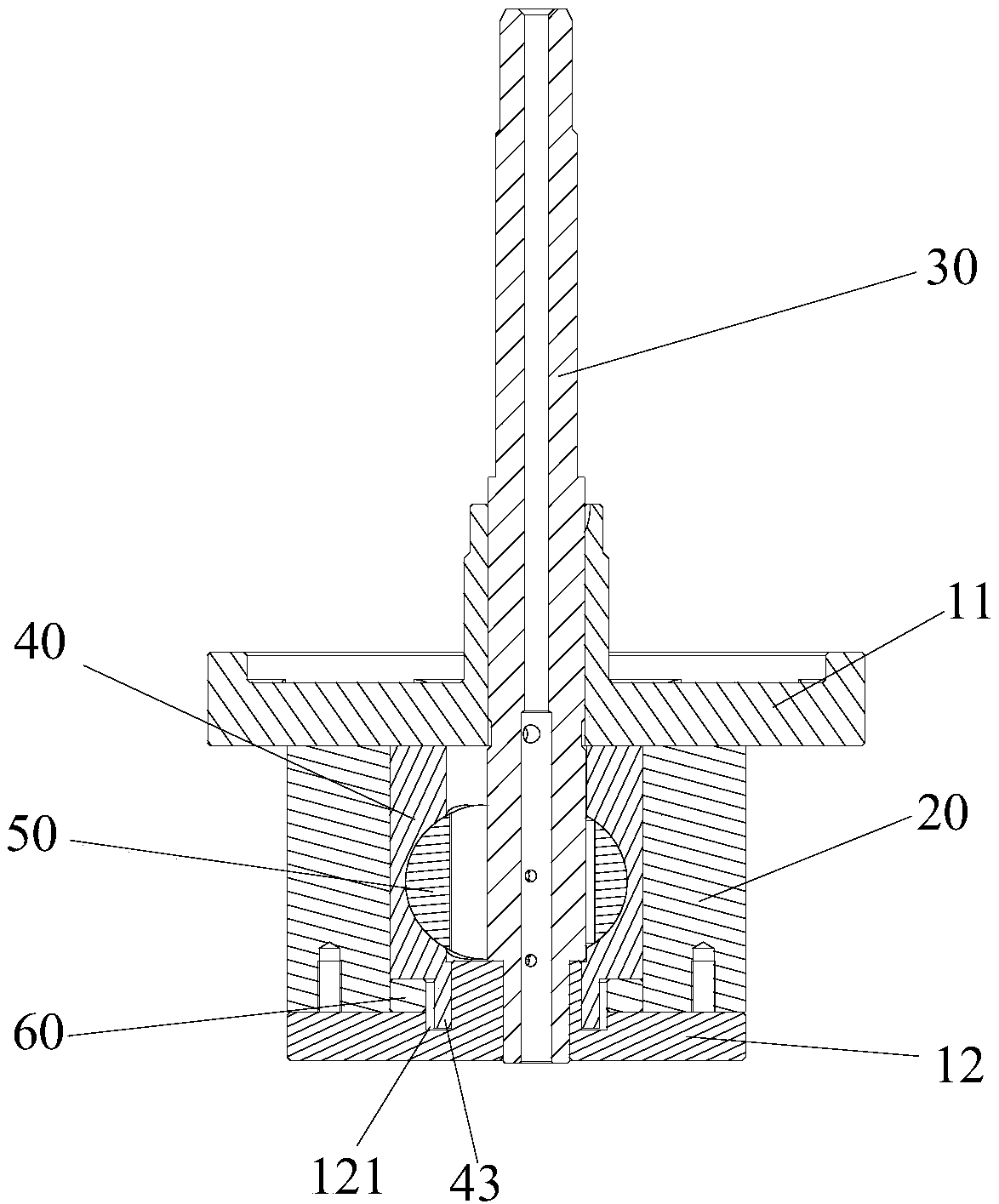
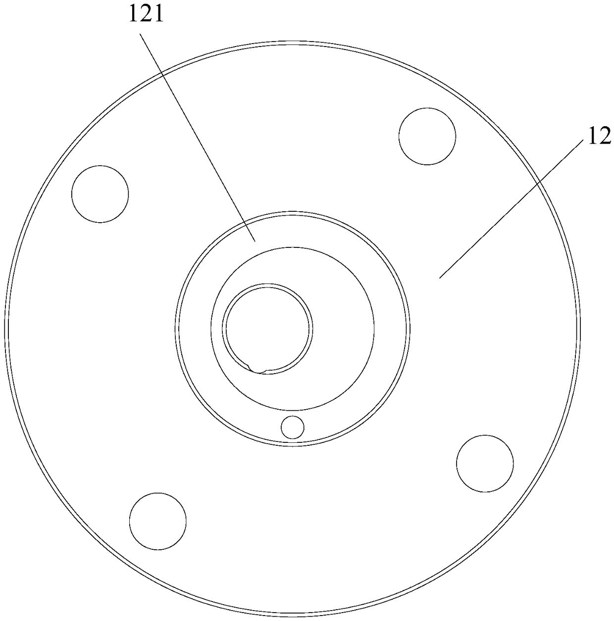
[0065] Such as Figure 1 to Figure 4 As shown, the pump body assembly includes a lower flange 12, a lower wear reducing ring 60, a cylinder 20 and a piston assembly. Wherein, the lower wear reducing ring 60 is located in the cylinder 20 , and the lower flange 12 is located below the cylinder 20 . The piston assembly is arranged in the cylinder 20. The piston assembly includes a piston sleeve 40 and a piston 50 slidably arranged in the piston sleeve 40. The lower wear-reducing ring 60 has a central hole, and the surface of the piston sleeve 40 facing the lower flange 12 has a stop protrusion. Lifting 43, the limit protrusion 43 extends into the center hole of the lower wear-reducing ring 60 and cooperates with the lower flange 12 to prevent the radial displacement of the piston sleeve 40 relative to the lower flange 12.

[0066] Applying the technical solution of this embodiment, during the operation of the pump body assembly, the limit protrusion 43 located at the lower end o...

Embodiment 2

[0074] The difference between the pump body assembly in the second embodiment and the first embodiment is that the structure of the lower flange 12 is different.

[0075] Such as Figure 5 to Figure 7 As shown, the surface of the lower flange 12 facing the piston sleeve 40 has a second extension portion 122, and the second extension portion 122 and the limit protrusion 43 limit the stop to prevent the piston sleeve 40 from radially occurring relative to the lower flange 12. displacement in the direction. Specifically, during the operation of the pump body assembly, the side surfaces of the second extension part 122 and the side surfaces of the limiting protrusion 43 can be limitedly fitted to prevent radial displacement between the two, thereby preventing the piston sleeve 40 from moving relative to the lower side. The displacement in the radial direction of the flange 12 ensures the stable operation of the piston sleeve 40 and improves the operational reliability and working...

Embodiment 3

[0083] The difference between the pump body assembly in the third embodiment and the first embodiment is that the structure of the upper flange 11 is different.

[0084] Such as Figure 8 to Figure 12 As shown, the surface of the upper flange 11 facing the piston sleeve 40 has a concave portion 111 , the first extension portion 41 protrudes into the concave portion 111 and stops with the concave portion 111 in the radial direction of the piston sleeve 40 . In this way, the first extension portion 41 of the piston sleeve 40 protrudes into the recess 111 of the upper flange 11 , so that the upper flange 11 can radially limit the piston sleeve 40 . During the operation of the pump body assembly, the concave portion 111 and the first extension portion 41 limit the stopper to ensure that the first extension portion 41 rotates in the concave portion 111 without moving the first extension portion 41 in the radial direction. position, to realize the limit and support of the upper fla...


PUM


Abstract

The invention provides a pump body assembly, fluid machinery and heat exchange equipment. The pump body assembly comprises a lower flange, a lower anti-friction ring, an air cylinder and a piston assembly, wherein the lower anti-friction ring is positioned in the air cylinder, and the lower flange is positioned below the air cylinder; the piston assembly is arranged in the air cylinder; the pistonassembly comprises a piston sleeve and a piston which is arranged in the piston sleeve in a sliding mode; a center hole is formed in the lower anti-friction ring; the surface, which faces towards thelower flange, of the piston sleeve is provided with a limiting bulge; and the limiting bulge extends into the center hole of the lower anti-friction ring, and is in limiting fit to the lower flange to prevent the piston sleeve from displacement in a radial direction relative to the lower flange. The pump body assembly effectively solves the problems that the piston of the pump body assembly in the prior art is liable to have eccentric rotation and the working efficiency of the pump body assembly is affected.

Description

technical field [0001] The invention relates to the technical field of pump body components, in particular to a pump body component, fluid machinery and heat exchange equipment. Background technique [0002] At present, during the operation of the pump body assembly, the piston sleeve is prone to eccentricity and tilt rotation, which causes the piston sleeve to easily rub against the cylinder and the piston, seriously affecting the working efficiency and performance of the pump body assembly. Contents of the invention [0003] The main purpose of the present invention is to provide a pump body assembly, fluid machinery and heat exchange equipment to solve the problem in the prior art that the piston sleeve of the pump body assembly is prone to eccentric rotation and affects the working efficiency of the pump body assembly. [0004] In order to achieve the above object, according to one aspect of the present invention, a pump body assembly is provided, including: a lower fl...

Claims


Application Information

Patent Timeline
IPC IPC(8): F04C18/00F04C29/00
CPCF04C18/00F04C29/00F04C2240/10F04C2240/20F04C2240/60F04C2240/80F04C2230/603F04C18/344F01C1/344F04B19/22F16J1/005F16J9/12
Inventor 魏会军徐嘉杜忠诚杨森李直梁社兵任丽萍张荣婷史正良刘喜兴
Owner GREE ELECTRIC APPLIANCES INC
Why Eureka
Try Eureka