Eureka AIR delivers breakthrough ideas for toughest innovation challenges, trusted by R&D personnel around the world.

Capsule drying rotary cage

A drying and capsule technology, which is applied in the direction of drying solid materials, drying chamber/container, drying gas arrangement, etc., can solve the problems of low production efficiency and uneven drying of capsules, and achieve improved work efficiency, convenient operation and use, and good stability Effect

Pending Publication Date: 2018-11-13
SHANDONG KANGFUSEN BIOTECH CO LTD
View PDF0 Cites 1 Cited by
  • Summary
  • Abstract
  • Description
  • Claims
  • Application Information

AI Technical Summary

Problems solved by technology

[0002] At present, in the capsule manufacturing process, drying the capsules is an indispensable step. Now, the capsules are usually put into the drying tumbler and the capsules are dried by a drying fan. However, due to the existing drying tumbler They are all cylindrical, so when turning, the capsules will accumulate at the bottom of the drying cage, so that the capsules will be dried unevenly and the production efficiency will be low

Method used


Image

  • Capsule drying rotary cage
  • Capsule drying rotary cage

Examples


Embodiment Construction

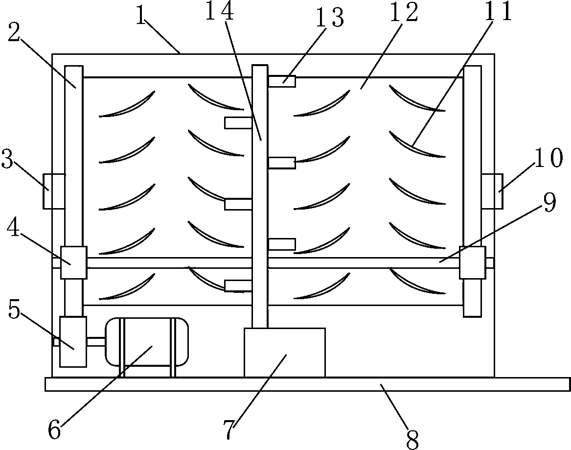
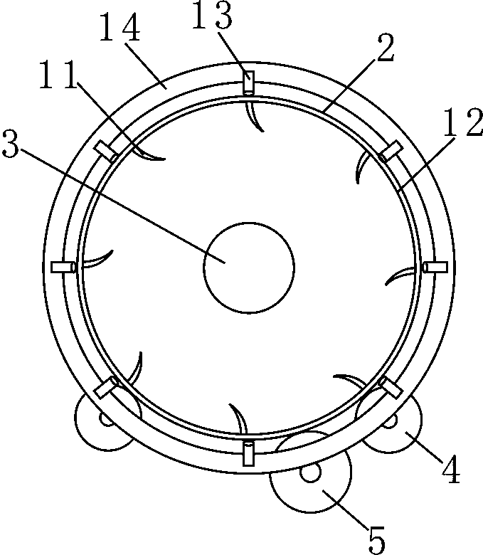
[0008] Now refer to the attached figure 1 And attached figure 2 , described in conjunction with the embodiment as follows: a capsule drying tumbler, including a drying cage 12, a drying part, a support plate 8 and a motor 6, the housing 1 is fixedly arranged on the support plate 8, and the two sides of the housing 1 are respectively Rotation is provided with a rotating shaft 9, and the two ends of described rotating shaft 9 are respectively fixedly provided with a supporting gear 4, and the two ends of described drying cage 12 are respectively fixedly provided with a driven gear 2, and described driven gear 2 and supporting gear 4 meshing, the drying cage 12 is rotationally connected with the supporting gear 4 through the driven gear 2, the drying cage 12 is erected on the supporting gear 4 through the driven gear 2, and one end of the drying cage 12 is provided with a feeding port 3 , the other end of the drying cage 12 is provided with a discharge port 10, the cage wall of...


PUM


Abstract

A capsule drying rotary cage comprises a drying cage, a drying portion, a supporting plate and a motor. A shell is fixedly arranged on the supporting plate. The inner two sides of the shell are each rotationally provided with a rotating shaft. The two ends of each rotating shaft are each fixedly provided with a supporting gear. The two ends of the drying cage are each fixedly provided with a driven gear. The driven gears are meshed with the supporting gears. The drying cage is rotationally connected with the supporting gears through the driven gears. The drying cage is erected on the supporting gears through the driven gears. One end of the drying cage is provided with a feeding opening. The other end of the drying cage is provided with a material outlet. The supporting plate below the drying cage is fixedly provided with a motor through a frame. An output shaft of the motor is fixedly provided with a driving gear. The driving gear is meshed with the driven gear. The supporting plate is fixedly provided with a motor on one side of the drying cage. Lifting partition plates are arranged on the inner wall of the drying cage in array. By the adoption of the capsule drying rotary cage,capsules can be rapidly and comprehensively dried, and the work efficiency is improved.

Description

technical field [0001] The invention relates to the field of capsule manufacturing, in particular to a capsule drying tumbler. Background technique [0002] At present, in the capsule manufacturing process, drying the capsules is an indispensable step. Now, the capsules are usually put into the drying tumbler and the capsules are dried by a drying fan. However, due to the existing drying tumbler They are all cylindrical, so when turning, the capsules will accumulate at the bottom of the drying cage, so that the capsules will be dried unevenly and the production efficiency will be low. Contents of the invention [0003] The object of the present invention is to overcome the disadvantages of the prior art, and provide a capsule drying tumbler, which can quickly and comprehensively dry the capsules and improve work efficiency. [0004] A capsule drying tumbler according to the present invention includes a drying cage, a drying part, a support plate and a motor, the outer she...

Claims


Application Information

Patent Timeline
IPC IPC(8): F26B11/04F26B21/00F26B25/02F26B25/16
CPCF26B11/04F26B21/004F26B25/02F26B25/16
Inventor 宋文秀李增强
Owner SHANDONG KANGFUSEN BIOTECH CO LTD
Why Eureka
Eureka Blog
Learn More