
Detection structure for water purifier and control method of detection structure

A technology for detecting structures and water purifiers, used in instruments, measuring devices, scientific instruments, etc., can solve problems such as difficult alignment, water ingress and damage to connectors, and achieve the effect of stable power supply

Pending Publication Date: 2018-11-13
FOSHAN VIOMI ELECTRICAL TECH +1
View PDF0 Cites 0 Cited by
  • Summary
  • Abstract
  • Description
  • Claims
  • Application Information

AI Technical Summary

Problems solved by technology

The male end (or female end) of the connector is installed on the detection module side, and the female end (or male end) of the connector is installed on the corresponding interface on the host. However, since the detection module needs to be often pulled out of the host and used alone, it is docked through the connector. Due to the relatively large module and the blind spot of human vision, it is not easy to align when plugging in, and the PIN pin is easy to be crooked or broken.
In addition, the connector and the water quality detection probe are on the same connection surface, and water will overflow or splash to the position of the connector when plugging and unplugging, causing water to enter the connector, causing corrosion and short circuit damage

Method used


Image

  • Detection structure for water purifier and control method of detection structure
  • Detection structure for water purifier and control method of detection structure
  • Detection structure for water purifier and control method of detection structure

Examples


Embodiment Construction

[0058] The technical solutions of the present invention will be further described below in conjunction with the accompanying drawings and through specific implementation methods.

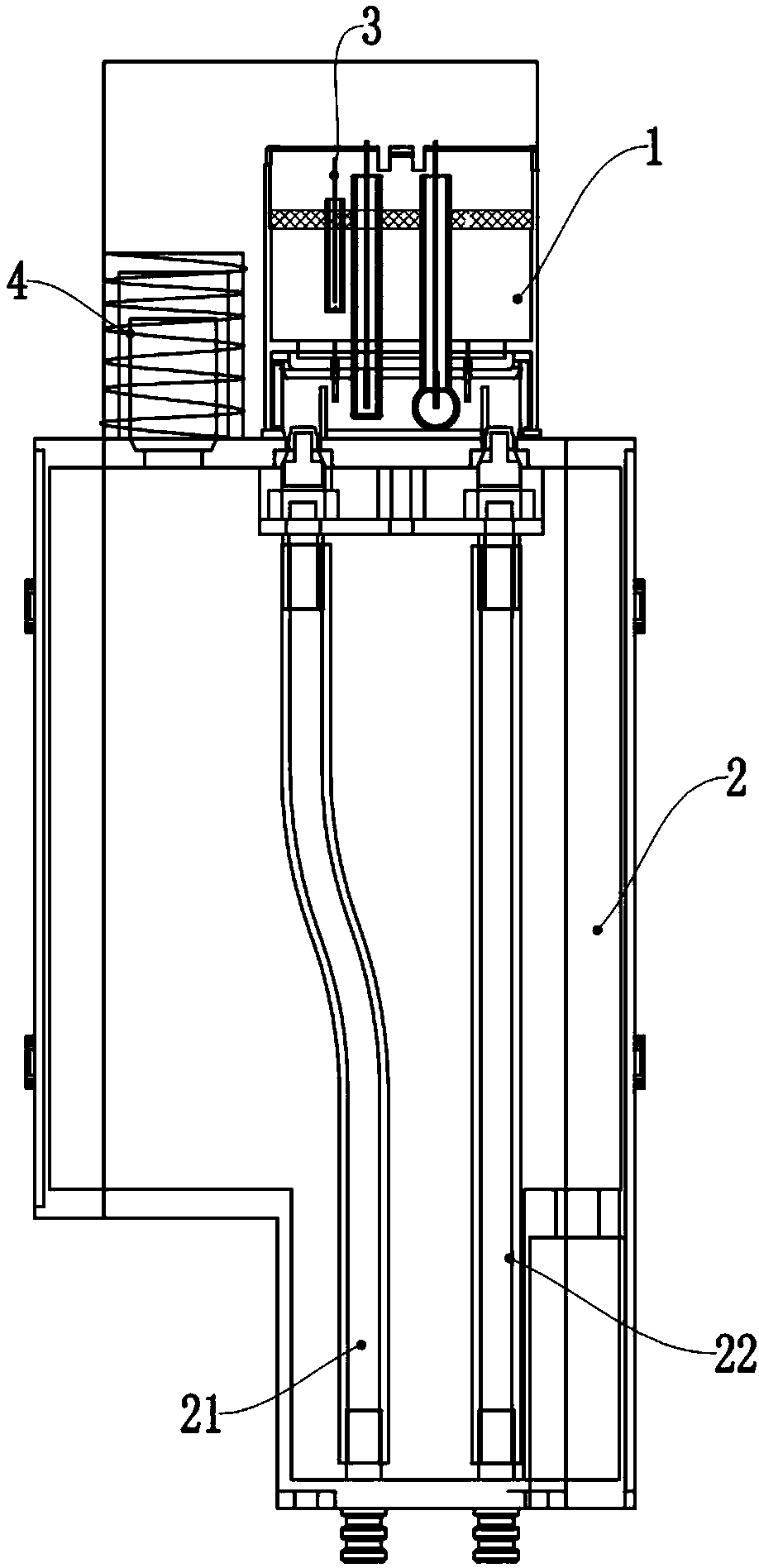
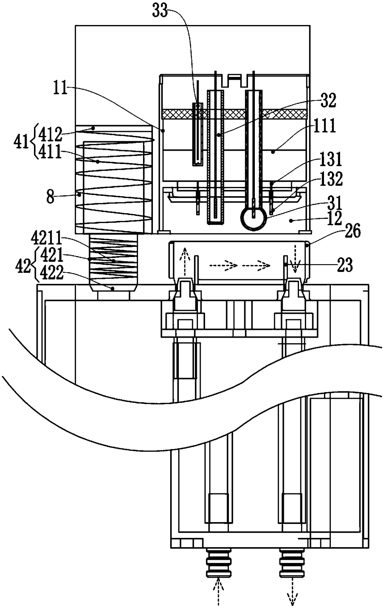
[0059] A detection structure for a water purifier, comprising: a detection shell cap 1, a housing 2, a power receiving device 4 and an application device 3;

[0060] The detection shell cap 1 is detachably connected to the housing 2; the application device 3 is arranged in the housing 2;

[0061] The power receiving device 4 includes: a detection module 41 and a host component 42;

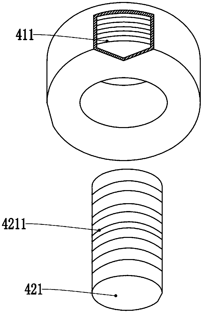
[0062]The detection module 41 includes: a receiving module 411 and an information receiving board 412; the receiving module 411 is connected to the information receiving board 412;

[0063] The host assembly 42 includes: a host transmitter module 421 and a host driver board 422; the host transmitter module 421 is connected to the host driver board 422; the host transmitter module 421 is provided with a transmitter coil ...


PUM


Abstract

The invention discloses a detection structure for a water purifier and a control method of the detection structure. In the detection structure, a detection shell cap is connected with the shell; an application device is arranged inside the shell; a power receiving device comprises a detection module and a main machine assembly; the detection module comprises a receiving module and an information receiving plate; the receiving module is connected with the information receiving plate; the main machine assembly comprises a main machine transmitting module and a main machine driving plate; the main machine transmitting module is connected with the main machine driving plate; the main machine transmitting module is connected with a transmitting coil; an input port is formed in one of the detection shell cap and the shell; the main machine transmitting module is arranged in the other one of the detection shell cap and the shell; and the main machine transmitting module and the receiving module are connected inside the input port in a coupling manner, and then the detection module is mounted on the main machine assembly till the input port is completely sealed. By adopting the control method, the main machine assembly supplies power to the detection module and the application device when the transmitting coil is coupled with the receiving module. Due to the design, an electric interface is completely isolated from water, so that the problems that water easily enter a connector and thus corrosion damage or short circuits can be caused, can be solved.

Description

technical field [0001] The invention relates to the technical field of water purifier detection, in particular to a detection structure for a water purifier and a control method thereof. Background technique [0002] The power supply and signal connection between the water purifier detection module and the host in the prior art are all completed through wired connectors. The male end (or female end) of the connector is installed on the detection module side, and the female end (or male end) of the connector is installed on the corresponding interface on the host. However, since the detection module needs to be often pulled out of the host and used alone, it is docked through the connector. Due to the relatively large module and being in the blind spot of human vision, it is not easy to align when plugging in, and the PIN pin is easy to be crooked or broken. In addition, the connector and the water quality detection probe are on the same connection surface. When plugging and...

Claims


Application Information

Patent Timeline
IPC IPC(8): G01N27/00
CPCG01N27/00
Inventor 陈小平林创荣
Owner FOSHAN VIOMI ELECTRICAL TECH
Learn More