
Optical fiber scanning projection objective lens and optical fiber scanning projection equipment

An optical fiber scanning and projection objective lens technology, applied in optics, optical components, instruments, etc., can solve problems such as distortion around the image, eliminate chromatic aberration, ensure color effects, and avoid excessive field curvature.

Active Publication Date: 2018-11-13
CHENGDU IDEALSEE TECH
View PDF15 Cites 6 Cited by
  • Summary
  • Abstract
  • Description
  • Claims
  • Application Information

AI Technical Summary

Problems solved by technology

[0005] The embodiment of the present invention provides an optical fiber scanning projection objective lens and an optical fiber scanning projection device, which are used to solve the technical problem existing in the prior art that the output of the optical fiber scanning is a curved surface image, resulting in obvious distortion around the projected image.

Method used


Image

  • Optical fiber scanning projection objective lens and optical fiber scanning projection equipment
  • Optical fiber scanning projection objective lens and optical fiber scanning projection equipment
  • Optical fiber scanning projection objective lens and optical fiber scanning projection equipment

Examples


Embodiment Construction

[0032] The following will clearly and completely describe the technical solutions in the embodiments of the present invention with reference to the accompanying drawings in the embodiments of the present invention. Obviously, the described embodiments are only some, not all, embodiments of the present invention. Based on the embodiments of the present invention, all other embodiments obtained by persons of ordinary skill in the art without creative efforts fall within the protection scope of the present invention.

[0033] Embodiments of the present invention provide an optical fiber scanning projection objective lens and a fiber scanning projection device to solve the technical problem in the prior art that the output of the optical fiber scanning is a curved surface image, resulting in obvious distortion around the projected image.

[0034] The first aspect of the embodiment of the present invention provides an optical fiber scanning projection objective lens, please refer to...


PUM


Abstract

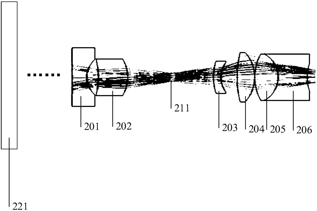
The invention discloses an optical fiber scanning projection objective lens and optical fiber scanning projection equipment. The optical fiber scanning projection objective lens comprises six lenses and a diaphragm which are arranged on a common optical axis. The optical fiber scanning projection objective lens comprises, sequentially from a position facing a projection image surface, a first lenswith negative focal power; a second lens with positive focal power; a diaphragm, a third lens with negative focal power, a fourth lens with positive focal power; a fifth lens with positive focal power and a sixth lens with negative focal power, wherein the fifth lens and the sixth lens are combined to form a lens set with positive focal power. Due to the fact that the technical scheme of positiveand negative lens separation and meniscus lens is adopted, the optical fiber scanning projection objective lens in the embodiment of the invention can be used for correcting the curved surface imageoutput by the optical fiber scanning. The problem that the curved surface image output by the optical fiber scanning is large in field curvature after being amplified and projected is avoided, and thevisual effect of the optical fiber scanning to a user is guaranteed.

Description

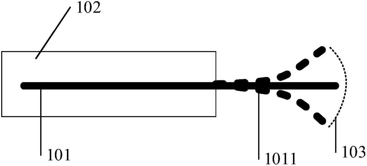
technical field [0001] The invention relates to the field of optical lenses, in particular to an optical fiber scanning projection objective lens and an optical fiber scanning projection device. Background technique [0002] Optical fiber scanning refers to controlling the scanning optical fiber to vibrate regularly, and at the same time color-modulate the light beam emitted by the optical fiber, and supplemented by precise control algorithms. After the light beam is incident on the projection screen, combined with the visual persistence effect of the human eye, that is The purpose of outputting images can be achieved. [0003] However, please refer to figure 1 , figure 1 It is a schematic diagram of an optical fiber scanning device in the prior art, such as figure 1 As shown, the part of the scanning fiber 101 protruding from the scanning device 102 is called the fiber cantilever 1011. When scanning, the fiber cantilever 1011 essentially forms a curved surface 103 with t...

Claims


Application Information

Patent Timeline
IPC IPC(8): G02B13/00G03B21/00G03B21/20
CPCG02B13/00G03B21/00G03B21/20
Inventor 周旭东
Owner CHENGDU IDEALSEE TECH
Learn More