Sub-health online recognition and diagnosis method based on performance monitoring data

A technology of monitoring data and diagnosis method, which is applied in the field of sub-health online identification and diagnosis based on performance monitoring data, can solve the problems of sub-health status of equipment, failure to reflect the real status of equipment, and inability to diagnose the working status of equipment in real time. Reduce losses and make up for the effect of easy misdiagnosis

Active Publication Date: 2018-11-13
BEIHANG UNIV
View PDF5 Cites 6 Cited by
  • Summary
  • Abstract
  • Description
  • Claims
  • Application Information

AI Technical Summary

Problems solved by technology

However, during the operation of the equipment, it does not always work efficiently and with high accuracy, and there is still a sub-health state; therefore, the two-state model based on normal and fault will misdiagnose the sub-health state as a normal state or a fault state, and cannot reflect real state of the device
[0003] At present, in engineering applications, the data of equipment failure status is generally obtained through FMECA report, so as to identify the equipment failure status; however, it is difficult to obtain the sub-health status of the equipment through the hardware structure and working mechanism of the equipment. Over time, the status data of the equipment is gradually obtained by monitoring the operating status of the equipment and the data changes of the monitoring points, and then the sub-health status is identified based on the status data
[0004] However, this method of identifying and diagnosing the sub-health state of the equipment based on the state data of the equipment operation is currently mainly used offline, that is, the sub-health state is diagnosed by analyzing the historical state data of the equipment, so the working status of the equipment cannot be diagnosed in real time.

Method used


Image

  • Sub-health online recognition and diagnosis method based on performance monitoring data
  • Sub-health online recognition and diagnosis method based on performance monitoring data
  • Sub-health online recognition and diagnosis method based on performance monitoring data

Examples


Embodiment

[0115] In this embodiment, a DC power conversion circuit is selected, which includes three parts: 18V power supply circuit, 18V to 12V power conversion circuit and 12V to 5V power conversion circuit.

[0116] The DC power conversion circuit is provided with 3 monitoring points, which are the output voltage VOUT of the 18V power supply, the output voltage S+12V of the 12V power supply, and the output voltage S+5V of the 5V power supply. The voltage output of these three monitoring points is monitored separately, and the voltage data is collected with a data card, so as to evaluate the health status of the circuit.

[0117] The voltages of the three monitoring points VOUT, S+12V, and S+5V all reflect the key functions of the circuit, and the voltage outputs of these three monitoring points are independent of each other, so the voltage monitoring values ​​of these three monitoring points are selected for evaluation The health status of the DC power conversion circuit; record VOUT...


PUM


Abstract

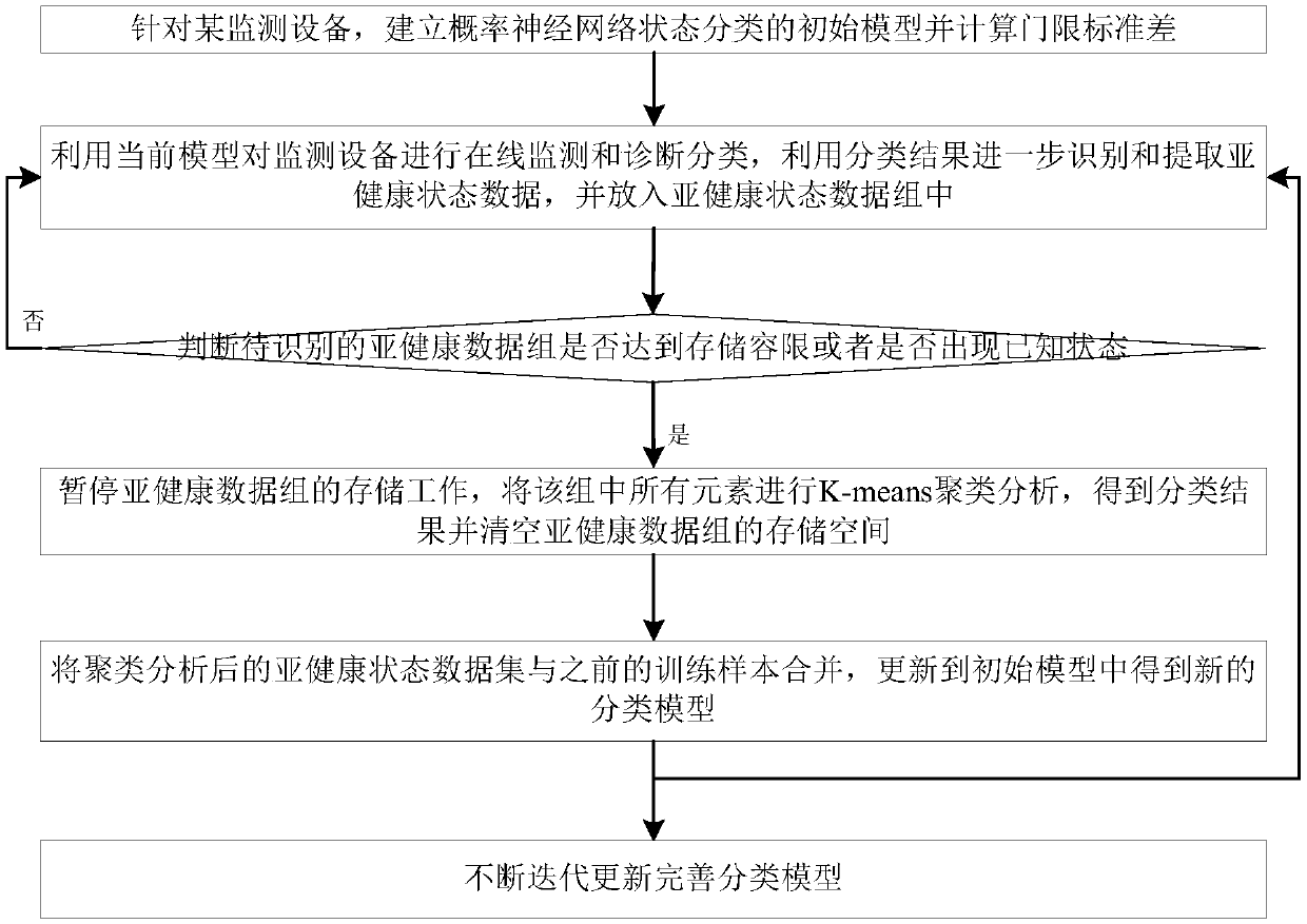
The invention discloses a sub-health online recognition and diagnosis method based on performance monitoring data, and belongs to the technical field of fault diagnosis. The method includes the stepsof establishing an initial model of a probability neural network state classification and calculating the threshold standard deviation, carrying out on-line monitoring and diagnosis classification onmonitored equipment by utilizing the current model, and further identifying and extracting sub-health state data and putting the sub-health state data into a sub-health state data set; if the sub-health data set to be recognized reaches a storage tolerance or a known state appears, pausing the storage work, subjecting all elements in the set to K-means clustering analysis to obtain a classification result, and clearing the storage space of the sub-health data set, combining the sub-health state data set after clustering analysis with a previous training sample, and updating to the initial model to obtain a new classification model; repeating the previous steps to identify the sub-health state, and carrying out timely maintenance when the fault state occurs. According to the method, timelyand effective measures are adopted according to the state of the equipment, and loss caused by faults is reduced.

Description

technical field [0001] The invention belongs to the technical field of fault diagnosis, and relates to a sub-health online identification and diagnosis method based on performance monitoring data. Background technique [0002] The traditional fault diagnosis method includes two states, normal and fault, and based on this, a diagnostic model is constructed. However, during the operation of the equipment, it is not always efficient and high-accuracy work, and there is a sub-health state; therefore, the two-state model based on normal and fault will misdiagnose the sub-health state as a normal state or a fault state, which cannot reflect true state of the device. [0003] At present, in engineering applications, the data of equipment failure status is generally obtained through FMECA reports, so as to identify the equipment failure status; however, it is difficult to obtain the sub-health status of the equipment through the hardware structure and working mechanism of the equip...

Claims


Application Information

Patent Timeline
Patent Type & Authority Applications(China)
IPC IPC(8): G05B23/02G06K9/62G06N3/04G06N3/08
CPCG05B23/0256G06N3/08G06N3/045G06F18/23213G06F18/214
Inventor 石君友郭绪浩何庆杰邓怡
Owner BEIHANG UNIV
Why Eureka
Try Eureka