A self-powered inner-cooled permanent magnet motor with flipping magnetic pole speed regulation mechanism

A permanent magnet motor and speed regulation technology, which is applied in the field of permanent magnet motors and self-cooled permanent magnet motors, can solve the problems of limited operating performance of permanent magnet motors, high requirements for control systems, and complex operating systems of permanent magnet motors.

Inactive Publication Date: 2019-04-19
HARBIN UNIV OF SCI & TECH
View PDF6 Cites 1 Cited by
  • Summary
  • Abstract
  • Description
  • Claims
  • Application Information

AI Technical Summary

Problems solved by technology

[0002] Due to the limitation of its own inherent characteristics, the speed regulation of permanent magnet motors cannot achieve flexible pole-changing speed regulation like electric excitation synchronous motors. In order to achieve speed regulation, frequency conversion speed regulation is usually used. The speed method has higher requirements on the control system when the permanent magnet motor is running at high speed, and the operating performance of the permanent magnet motor is limited to a certain extent
In addition, since the permanent magnet material will be irreversibly demagnetized under the influence of high temperature, the permanent magnet motor is usually cooled by forced cooling. This forced cooling method requires a fan pressure head or a cooler, which makes the operation system of the entire permanent magnet motor complicated. High cost and not easy to maintain

Method used


Image

  • A self-powered inner-cooled permanent magnet motor with flipping magnetic pole speed regulation mechanism
  • A self-powered inner-cooled permanent magnet motor with flipping magnetic pole speed regulation mechanism
  • A self-powered inner-cooled permanent magnet motor with flipping magnetic pole speed regulation mechanism

Examples


Embodiment

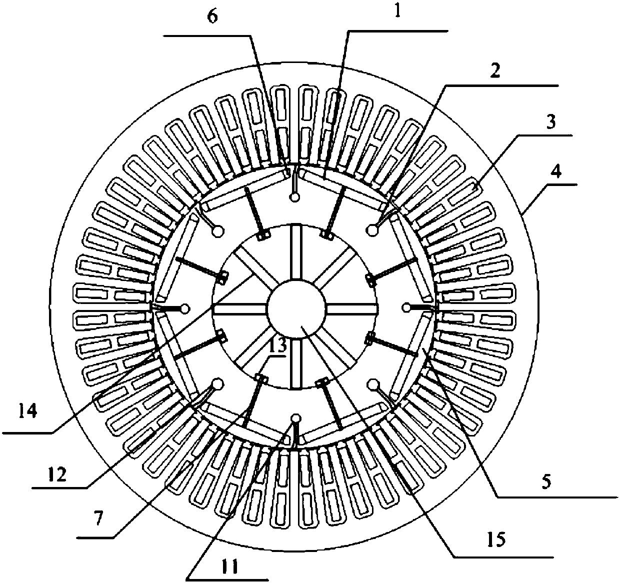
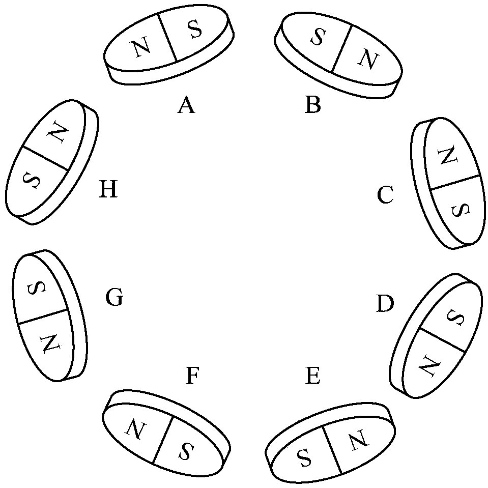
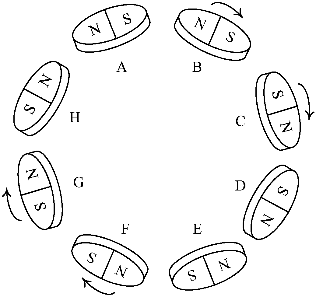
[0027] Example: see figure 1 , a self-operated internally cooled permanent magnet motor with a flipping magnetic pole speed regulation mechanism in this embodiment, including a permanent magnet 1, a stator winding 3, a stator core 4, a rotor core 5, a rotating rod 7, a rotating screw handle 13, and a rotor bracket 14 and rotating shaft 15; a plurality of permanent magnets 1 are cake-shaped structures, each permanent magnet 1 is connected with a rotating rod 7, and is tightened inside the rotor core 5 by rotating the screw handle 13; the stator winding 3 is embedded in the stator core 4 slots; the rotor core 5 has a plurality of circumferentially evenly distributed rotor internal cooling ventilation slots 2, the number of permanent magnets 1 and rotor internal cooling ventilation slots 2 is the same, and the permanent magnets 1 and rotor internal cooling ventilation slots 2 are arranged alternately ; The magnetic potential direction of each independent permanent magnet 1 on the...


PUM


Abstract

The invention provides a self-powered internally cooled permanent magnet motor of an overturning magnetic pole speed-regulation mechanism, and belongs to the technical field of electric engineering. Control difficulty of a variable-frequency speed-regulation system during high-speed running of the permanent magnet motor is reduced by a rotary magnetic pole speed-change mode, multi-gear speed change of low speed, middle speed and high speed of a constant-frequency lower permanent magnet motor are finished, the speed-regulation range of the motor is broadened, and thus, the motor runs at high performance in a wide speed range. According to the technical scheme, the position of a pie permanent magnet is adjusted by controlling rotation of a rotating rod, multi-gear speed change of low speed,middle speed and high speed can be realized, and the control difficulty of the variable-frequency speed-regulation system during high-speed running of the motor is reduced favorably; and moreover, a self-powered tangential air-suction-radial air-guiding-axial exhaust integrated ventilating groove is formed in a rotor side, the cooling system is simple in structure, auxiliary equipment such as a fan pressure head and a cooler in a forced cooling mode is omitted, maintenance is facilitated, self-powered cooling on the rotor is realized by an automatic wind inducing mode, and temperature rising of the rotor and the permanent magnet is reduced effectively.

Description

technical field [0001] The invention relates to a permanent magnet motor with a speed regulation mechanism, in particular to a self-powered inner-cooled permanent magnet motor with a flipping magnetic pole speed regulation mechanism, and belongs to the technical field of electrical engineering. Background technique [0002] Due to the limitation of its own inherent characteristics, the speed regulation of permanent magnet motors cannot achieve flexible pole-changing speed regulation like electric excitation synchronous motors. In order to achieve speed regulation, frequency conversion speed regulation is usually used. The speed method has higher requirements on the control system when the permanent magnet motor runs at high speed, and the operating performance of the permanent magnet motor is limited to a certain extent. In addition, since the permanent magnet material will be irreversibly demagnetized under the influence of high temperature, the permanent magnet motor is us...

Claims


Application Information

Patent Timeline
Patent Type & Authority Patents(China)
IPC IPC(8): H02K1/27H02K1/32H02K1/30H02K21/02H02K3/28
CPCH02K1/2753H02K1/30H02K1/32H02K3/28H02K21/028
Inventor 王立坤寇宝泉张赫周一恒郭庆波
Owner HARBIN UNIV OF SCI & TECH
Why Eureka
Try Eureka