
Centering-type anti-looseness bone nail for orthopedics surgery

An orthopaedic surgery and anti-loosening technology, applied in the field of bone nails, can solve problems such as alignment errors and unstable steel plate fixation, and achieve the effects of being beneficial to recovery, stable fixation, and not easy to loosen.

Inactive Publication Date: 2018-11-16
LUOYANG ORTHOPEDIC TRAUMATOLOGICAL HOSPITAL
View PDF6 Cites 3 Cited by
  • Summary
  • Abstract
  • Description
  • Claims
  • Application Information

AI Technical Summary

Problems solved by technology

[0003] In order to solve the deficiencies of the prior art, the object of the present invention is to provide a bone screw for self-centering and alignment, which is used to solve the alignment error between the steel plate and the broken bone mentioned in the above background, and the plate is not fixed properly. firm question

Method used


Image

  • Centering-type anti-looseness bone nail for orthopedics surgery
  • Centering-type anti-looseness bone nail for orthopedics surgery
  • Centering-type anti-looseness bone nail for orthopedics surgery

Examples


no. 1 approach )

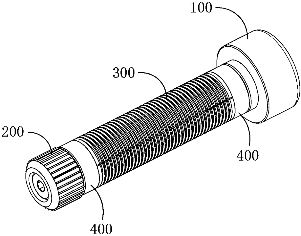
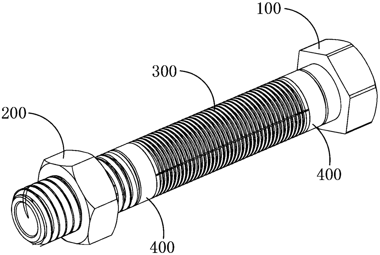
[0042] Such as Figure 7 As shown, the above-mentioned fixed section 200 includes a screw rod 240, and the screw rod 240 is a cylindrical structure arranged coaxially with the threaded rod 120. Distributed locking protrusions and the extension direction of the locking protrusions are parallel to the axial direction of the nail rod 240. A movable link is provided between the nail rod 240 and the smooth section of the threaded rod 120, and the nail rod 240 is connected through a flexible The piece is mounted on the smooth section of the threaded rod 120.

[0043] The center of the end face of the nail rod 240 away from the threaded rod 120 is provided with a mounting groove a, and the center of the end face of the nail rod 240 close to the threaded rod 120 is provided with a mounting groove b, the groove bottom of the mounting groove a, The center of the area between the groove bottoms of the installation groove b is provided with an installation hole a connected to the install...

no. 2 approach )

[0051] The difference between this embodiment and the first embodiment mainly lies in the structure of the fixing section 200 .

[0052] Such as Figure 8 As shown, the above-mentioned fixing section 200 includes a screw 210 and a nut 220 matched with the screw 210. The screw 210 is a cylindrical structure arranged coaxially with the threaded rod 120. The nut 220 is sleeved on the screw 210. Externally, a movable joint is provided between the screw rod 210 and the smooth section of the threaded rod 120 and the screw rod 210 is installed on the smooth section of the threaded rod 120 through the movable joint.

[0053] The center of the end face of the screw rod 210 away from the threaded rod 120 is provided with a mounting groove c, the center of the end face of the screw rod 210 close to the threaded rod 120 is provided with a mounting groove d, the bottom of the mounting groove a, the mounting groove The center of the area between the groove bottoms of b is provided with an ...


PUM


Abstract

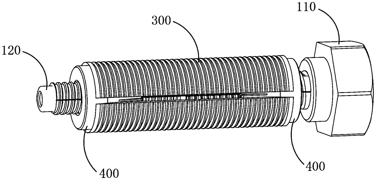
The invention provides a centering-type anti-looseness bone nail for orthopedics surgery. The bone nail comprises a tightening segment, a fixing segment, an expansion pat and a rotation part. The tightening segment is used for receiving the external tightening force, the fixing segment is used for fixing a broken bone, and the rotation part sleeves the tightening segment and provides expansion force for the expansion part; the expansion part expands under the expansion force, the tightening segment comprises a head and a threaded rod, and the threaded rod is coaxially and fixedly connected tothe head and can be divided into three parts including a threaded segment a, a smooth segment and a threaded segment b in sequence; the fixing segment comprises a nail rod, the nail rod is of a cylindrical structure which is coaxially arranged with the threaded rod, locking protrusions evenly distributed in the circumference direction of the nail rod are arranged on the outer circumference face ofthe nail rod, a movable connector is arranged between the nail rod and the smooth segment of the threaded rod, and the nail rod is installed on the smooth segment of the threaded rod through the movable connector.

Description

technical field [0001] The invention relates to a bone nail used for fixing between broken bones and steel plates of patients with fractures. Background technique [0002] The femur is also called the femur. Violent direct blows, falling from a high place, vehicle impact, rolling, etc. can cause femur fractures. When a femur fracture occurs, the lower limbs cannot move, and the fracture site is severely swollen, painful, and twisted or deformed. Deformities such as horns, sometimes the length of the lower limbs may be shortened. If there is an open wound at the same time, the condition will be more serious and often cause the patient to go into shock. The femur is the largest bone in the whole body. If it is not treated in time after the fracture, it may cause massive bleeding and nerve damage in the patient. and other serious complications, the fixation of broken bones in the prior art generally adopts plate internal fixation. It will make the fixing of the steel plate not...

Claims


Application Information

Patent Timeline
IPC IPC(8): A61B17/86
CPCA61B17/86A61B17/8625
Inventor 魏大平
Owner LUOYANG ORTHOPEDIC TRAUMATOLOGICAL HOSPITAL
Learn More