Engineering material treatment equipment capable of scattering sandy blocks through centrifugal force and being used in building field

A technology for processing equipment and centrifugal force, which is applied in the field of building material processing equipment and construction, can solve the problems of time-consuming shoveling, etc., and achieve the effect of reducing the impact of use

Inactive Publication Date: 2018-11-16
柯金炼
View PDF0 Cites 2 Cited by
  • Summary
  • Abstract
  • Description
  • Claims
  • Application Information

AI Technical Summary

Problems solved by technology

[0004] In view of the deficiencies in the existing technology, the purpose of the present invention is to provide a kind of engineering material processing equipment for the construction field that uses centrifugal force to break sand blocks, so as to solve the problem of agglomeration caused by the integration of other material particles after being blown by wind and rain in the prior art Defects that require workers to spend time shoveling, breaking up, and screening out large particles of impurities

Method used


Image

  • Engineering material treatment equipment capable of scattering sandy blocks through centrifugal force and being used in building field
  • Engineering material treatment equipment capable of scattering sandy blocks through centrifugal force and being used in building field
  • Engineering material treatment equipment capable of scattering sandy blocks through centrifugal force and being used in building field

Examples


Embodiment Construction

[0020] In order to make the technical means, creative features, goals and effects achieved by the present invention easy to understand, the present invention will be further described below in conjunction with specific embodiments.

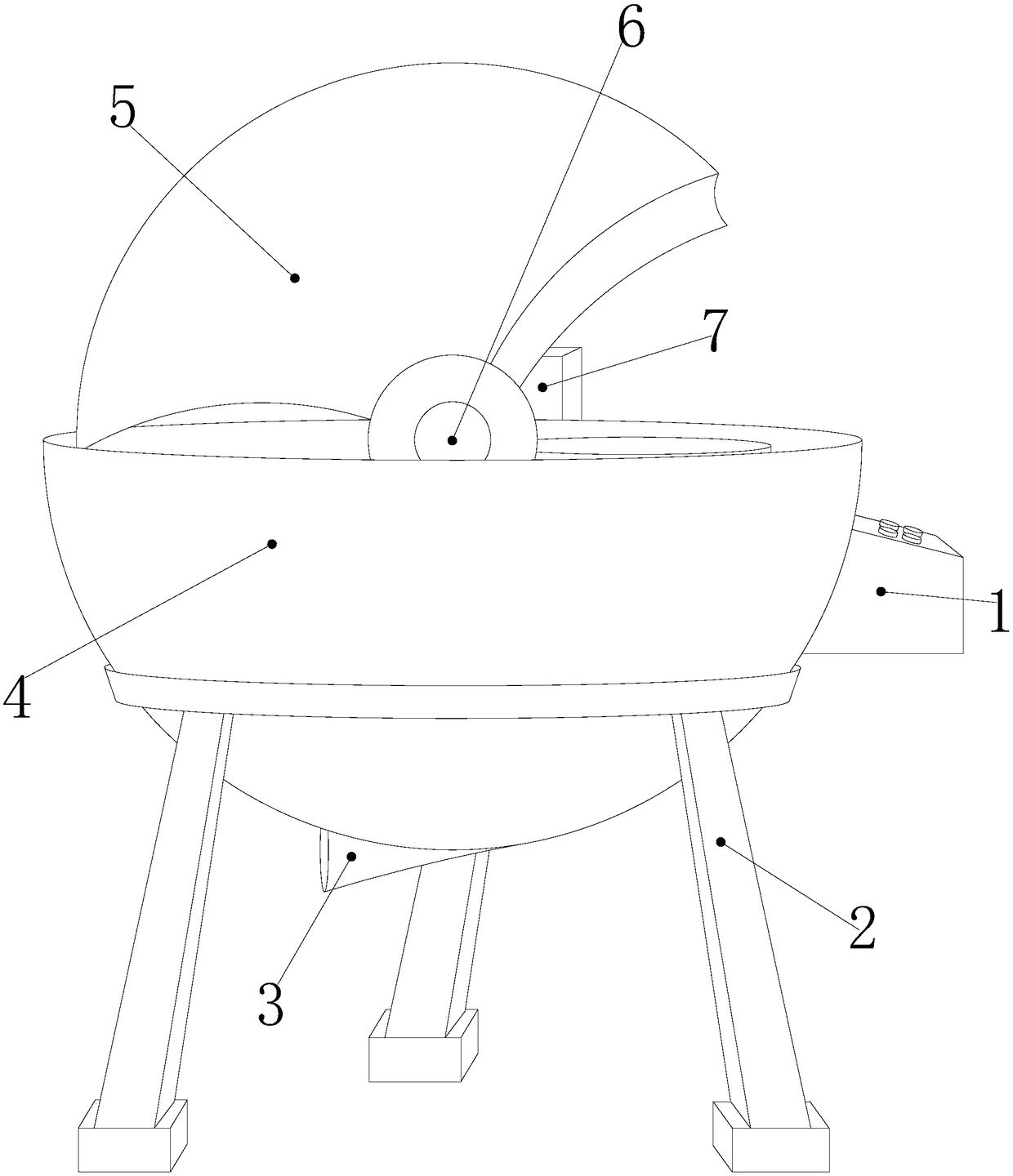
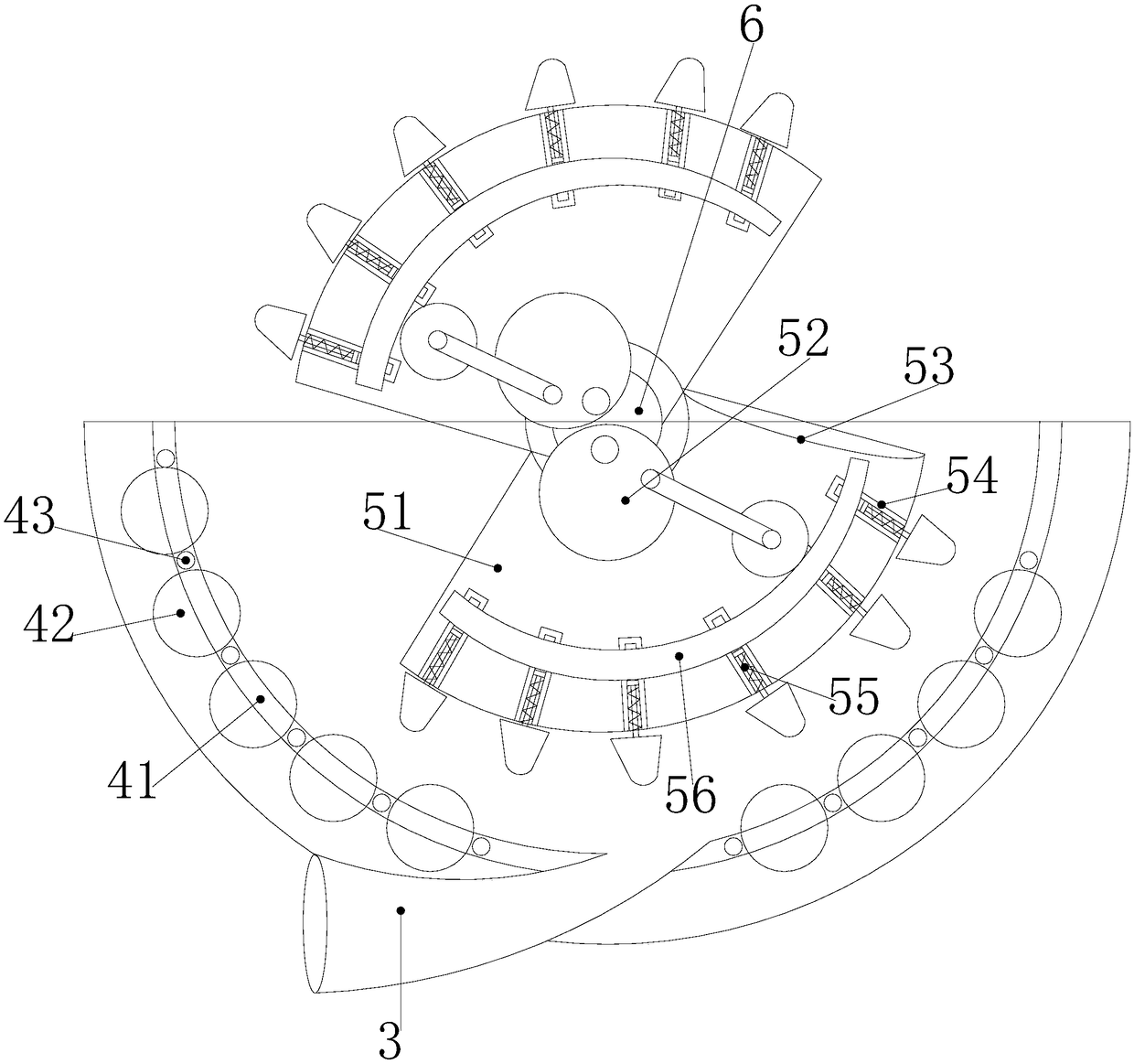
[0021] Such as Figure 1-2 As shown, the present invention provides a technical solution for engineering material processing equipment used in the construction field for centrifugal sand removal blocks: its structure includes a controller 1, a triangular support bracket 2, a loose sand discharge pipe 3, and a sand removal box 4 , deblocking device 5, rotating motor shaft 6, motor 7;

[0022] The triangular support bracket 2 is located at the lower end of the sand removal box 4, the loose sand discharge pipe 3 is connected to the bottom of the sand removal box 4 and is fixedly connected to form an integrated structure, and the sand removal box 4 is a semicircular structure , the deblocking device 5 is arranged inside the sand deblocking box 4 and ...


PUM


Abstract

The invention discloses engineering material treatment equipment capable of scattering sandy blocks through a centrifugal force and being used in the building field. The engineering material treatmentequipment structurally comprises a controller, a triangular supporting bracket, a scattered sand discharging pipe, a sand scattering tank body, a block scattering device, a rotating motor shaft and amotor, wherein the triangular supporting bracket is arranged at the lower end of the sand scattering tank body; the scattered sand discharging pipe is connected to the bottom part of the sand scattering tank body and is fixedly connected to the bottom part of the sand scattering tank body to form an integrated structure; the sand scattering tank body is of a semicircular structure; the block scattering device is arranged at the inner part of the sand scattering tank body and is movably connected with the sand scattering tank body; the rotating motor shaft penetrates through the middle part ofthe block scattering device and is movably connected with the middle part of the block scattering device. The engineering material treatment equipment disclosed by the invention has the beneficial effects that a fan-shaped rotor is driven to synchronously rotate through the rotating motor shaft, rapping bars in movable grooves can be pushed out one after another in different pushing time throughthe matching of centrifugal rotating wheels and pushing frames, the rapping bars can be in collision with caked sand through knocking heads so as to scatter the caked sand, and the manpower for shoveling and scattering sand can be saved; during a left-right moving process of the sand, the sand is in mutual friction with balls arranged at the bottom part of the sand scattering tank body, so that the volume of heavy particles blended in sand bodies can be reduced, and the using influence during construction is reduced.

Description

technical field [0001] The invention relates to the field of construction material processing equipment, more precisely, it is an engineering material processing equipment used in the field of construction for sand breaking by centrifugal force. Background technique [0002] A variety of materials are used in construction, such as concrete, sand, cement, etc. Among them, the main component of sand is silica, which is often used in various fields such as construction, road construction, and breeding due to its wide range of uses. Sand is piled in On the open field outside. [0003] After being exposed to wind and rain, it is easy to integrate different material particles and agglomerate. Before construction, workers need to shovel and break up, which consumes a lot of labor and wastes a lot of time to dry out large particles. Contents of the invention [0004] Aiming at the deficiencies of the existing technology, the purpose of the present invention is to provide a kind o...

Claims


Application Information

Patent Timeline
Patent Type & Authority Applications(China)
IPC IPC(8): B02C13/04B02C13/28B02C13/282B02C13/30B02C19/20
CPCB02C13/04B02C13/28B02C13/282B02C13/30B02C19/20B02C2013/2825
Inventor 柯金炼
Owner 柯金炼
Why Eureka
Try Eureka