Cavity-shaped separating structure for strong magnetic separation device

A technology of separation structure and strong magnetic separation, which is applied in magnetic separation, solid separation, chemical instruments and methods, etc., to achieve the effect of improving operation rate

Pending Publication Date: 2018-11-16
BGRIMM MACHINERY & AUTOMATION TECH CO LTD +1
View PDF0 Cites 0 Cited by
  • Summary
  • Abstract
  • Description
  • Claims
  • Application Information

AI Technical Summary

Problems solved by technology

For superconducting electromagnetic coils, limited by the cooling of superconducting coils, current leads, etc., it is impossible to realize the pr

Method used


Image

  • Cavity-shaped separating structure for strong magnetic separation device
  • Cavity-shaped separating structure for strong magnetic separation device
  • Cavity-shaped separating structure for strong magnetic separation device

Examples


specific Embodiment approach

[0019] The cavity-shaped separation structure for the strong magnetic separation device of the present invention, its preferred embodiment is:

[0020] It includes an outer cylinder, two sorting cavities are arranged in the outer cylinder, a balance cavity is set between the two sorting cavities, a transition cavity is respectively set near the outer ends of the two sorting cavities, and five cavities are arranged in the The outer cylinders are installed by pressing each other, and the ends of the outer cylinders are provided with a material inlet and a material outlet;

[0021] Both ends of the balance chamber are provided with sealing plugs;

[0022] The transition chamber includes a transition chamber inner chamber and a transition chamber outer chamber, and the sorting chamber includes a sorting chamber inner chamber and a sorting chamber outer chamber, and the sorting chamber outer chamber and the transition chamber outer chamber are connected to the outer cylinder Annul...

specific Embodiment

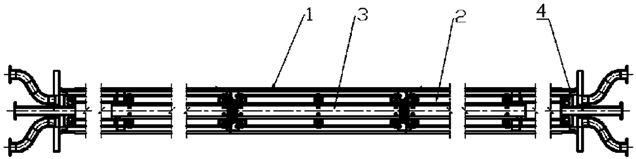
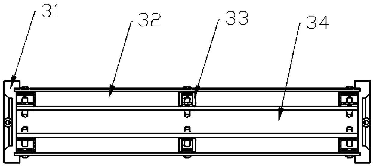
[0030] Such as figure 1 As shown, it is mainly composed of an outer cylinder 1, a separation chamber 2, a balance chamber 3, and a transition chamber 4, wherein the transition chamber 4, the separation chamber 2, and the balance chamber 3 are placed in the outer cylinder 1 in sequence.

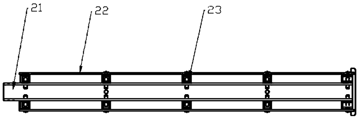
[0031] The sorting slurry enters the transition inner cavity 43 through the feed port 42 of the transition cavity 4, and then enters the sorting inner cavity 21 of the sorting cavity 2, and passes through the gap between the sorting inner cavity 21 and the sorting outer cavity 22 under pressure. The non-magnetic material enters the annular passage between the sorting outer chamber 22 and the outer cylinder 1 through the separation basket 23, and then enters the discharge port 41 through the annular passage between the transition chamber outer chamber 44 and the outer cylinder 1 , so as to realize the separation of magnetic materials and non-magnetic materials. In order to increase the working...


PUM


Abstract

The invention discloses a cavity-shaped separating structure for a strong magnetic separation device. The cavity-shaped separating structure comprises an outer cylinder. Two separation cavities are formed in the outer cylinder, a balance cavity is formed between the two separation cavities, transition cavities are formed in outer ends close to the two separation cavities correspondingly, the fivecavities are installed in the outer cylinder in a mutual pressing manner, and a feeding opening and a discharging opening are formed in the end portion of the outer cylinder. Sealing choke plugs are arranged at the two ends of the balance cavity. Ring-shaped channels are formed between outer cavities and the outer cylinder correspondingly. The ring-shaped channels communicate with the dischargingopening. Partition baskets are arranged in the separation cavities. The feeding opening mutually communicates with inner cavities of the transition cavities and inner cavities of the separation cavities in sequence. The cavity-shaped structure is utilized for freely coming in or out of a strong magnetic field, and separation operation of weak magnetic materials in the space of the strong magneticfield is achieved. The device ingeniously utilizes multi-layer separation operation of the cavities, and the operability can be improved remarkably for iron removal operation of slurry with the low content.

Description

technical field [0001] The invention relates to a magnetic separation and sorting device, in particular to a cavity-shaped separation structure for a strong magnetic separation device. Background technique [0002] There are various types of magnetic separation and sorting devices, among which, according to the type of sorting area, it can be divided into cylindrical, cylindrical, cavity and so on. Different types of sorting areas can be matched with different types of magnets to form different magnetic separation and separation devices. The cavity-shaped separation structure is suitable for matching hollow solenoid magnets to form a magnetic separation and separation device. [0003] The ordinary cavity-shaped separation mechanism is suitable for the natural flow of the sorting material flow. After the magnetic field acts on the magnetic material in the sorting material, the operation of the magnetic field with or without the magnetic field can be realized by controlling th...

Claims


Application Information

Patent Timeline
IPC IPC(8): B03C1/10
CPCB03C1/10
Inventor 王晓明刘永振冉红想葛丁魏红港彭欣苓史佩伟尚红亮
Owner BGRIMM MACHINERY & AUTOMATION TECH CO LTD
Why Eureka
Try Eureka