
Electric aspirator for removing contents in operating room

A content and suction device technology, which is applied in the field of electric suction devices for removing content in operating rooms, can solve the problems of complex internal structure and dead angle cleaning of the runner, and achieve simple structure, convenient cleaning, and good cooperation with the suction operation of the content Effect

Inactive Publication Date: 2022-06-28
JIANGSU TAIZHOU PEOPLES HOSPITAL
View PDF1 Cites 0 Cited by
  • Summary
  • Abstract
  • Description
  • Claims
  • Application Information

AI Technical Summary

Problems solved by technology

[0003] The purpose of the present invention is to solve the disadvantages of the prior art that there is a dead angle for cleaning the runner and the internal structure is relatively complicated, and proposes an electric suction device for removing contents in the operating room

Method used


Image

  • Electric aspirator for removing contents in operating room
  • Electric aspirator for removing contents in operating room
  • Electric aspirator for removing contents in operating room

Examples


Embodiment 1

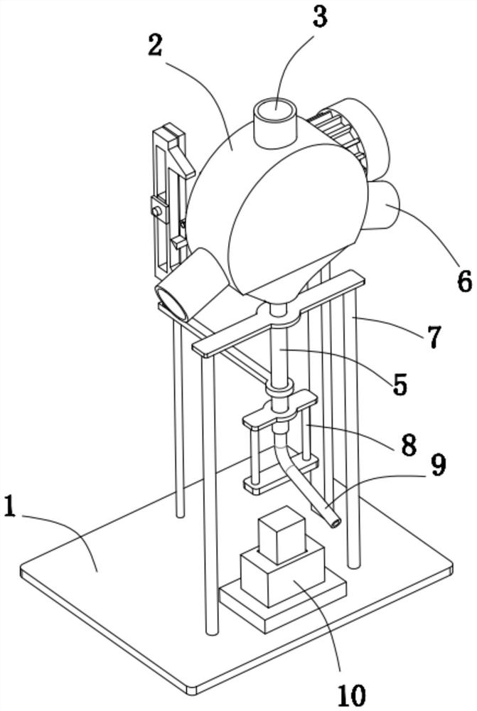
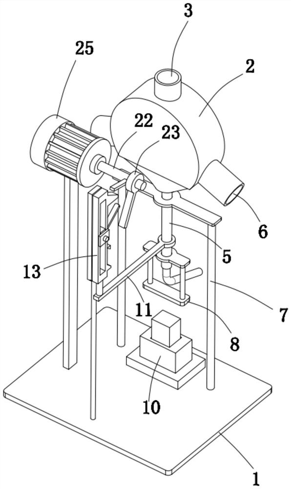
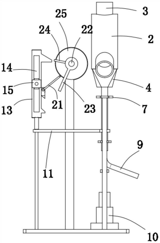
[0029] refer to Figure 1-10 , an electric suction device for removing contents in an operating room, including an electric negative pressure suction pump, the liquid outlet of the electric negative pressure suction pump is connected with a solid-liquid separation module through a pipeline, and the solid-liquid separation module includes a base 1 and a box body 2 , a box body 2 is arranged above the base 1, a liquid inlet pipe 3 communicating with it is fixed on the top of the box body 2, a flat cut is opened at the bottom of the box body 2, and a bag body 4 is covered and fixed on the flat cut, and the bag body 4 The open end is fixedly connected to the flat cut, the bottom of the bag body 4 is provided with and fixed with a guide tube 5, and the box body 2 above the flat cut is provided with and fixed with several discharge pipes 6 communicating with it internally. A hose 9 is installed on the end of the discharge pipe 6 far away from the box body 2 , and the guide tube 5 is...

Embodiment 2

[0040] refer to Figure 1-10 , as another preferred embodiment of the present invention, the difference from Embodiment 1 is that the liquid inlet pipe 3 is provided with an electromagnetic valve, and the liquid inlet pipe 3 is also equipped with a tee, and the other two interfaces of the tee are respectively connected to the electric negative The pressure suction pump and the temporary liquid storage tank are connected. The solenoid valve is connected to the control module, and the control module is also electrically connected to the motor 25. When the self-locking switch 10 is pressed and the motor 25 is powered on, the control module controls the solenoid valve to close so that the contents cannot enter the liquid inlet pipe. 3. The content will enter the temporary liquid storage tank through the tee until the self-locking switch 10 is pressed again. After the motor 25 is powered off, the control module will control the electromagnetic door to open so that the content can e...


PUM


Abstract

The invention relates to the technical field of medical instruments, in particular to an electric aspirator for removing contents in an operating room, which comprises an electric negative pressure suction pump, a liquid outlet of the electric negative pressure suction pump is communicated with a solid-liquid separation module through a pipeline, the solid-liquid separation module comprises a base and a box body, and the box body is arranged above the base; a liquid inlet pipe communicated with the interior of the box body is fixedly arranged at the top of the box body, a flat notch is formed in the bottom of the box body, a bag body covers and is fixed to the flat notch, the open end of the bag body is fixedly connected to the flat notch, and a flow guide pipe penetrates through and is fixed to the bottom of the bag body. A plurality of discharge pipes communicated with the interior of the box body are arranged and fixed on the box body above the flat notch in a penetrating manner, a hose is mounted at one end, far away from the box body, of each discharge pipe, the flow guide pipe is mounted on a driving module, and the driving module is used for driving the flow guide pipe to intermittently reciprocate relative to the box body. When the solid-liquid separation box is used, solid-liquid separation is achieved through the deformable bag body in the box body, and later cleaning is more convenient.

Description

technical field [0001] The invention relates to the technical field of medical instruments, in particular to an electric suction device for removing contents in an operating room. Background technique [0002] In the operating room, it is necessary to use an electric suction device to suck out the contents of the patient's body, and the sucked contents need to be separated from solid and liquid to facilitate subsequent treatment. In the invention patent of patent notification number CN 112370583B, an electric suction device for nursing care in an operating room is disclosed. The way to realize solid-liquid separation is mainly to set a runner in the casing for pulling out the solid content. The solid-liquid separation method, during use, because the interior of the electric suction device is in operation, the inner wall will inevitably be contaminated with residual content. After the operation is completed, it needs to be cleaned with disinfectant water to avoid later The r...

Claims


Application Information

Patent Timeline
Patent Type & Authority Applications(China)
IPC IPC(8): A61M1/00B01D29/27B01D29/60B01D29/70B01D29/94
CPCB01D29/27B01D29/60B01D29/70B01D29/94A61M2205/75B01D2221/10
Inventor 孙洁窦红梅刘静王妍陈诚
Owner JIANGSU TAIZHOU PEOPLES HOSPITAL
Learn More