Flow gas equilibrating device

A technology of passing air and equalizing holes, which is applied in the direction of steam flow control, electrostatic effect separation, solid separation, etc. It can solve the problems of reduced electrostatic dust removal time, increased flow rate of flue gas 2, and influence on dust removal effect, etc.

Pending Publication Date: 2018-11-16
江苏蓝博环保机械有限公司
View PDF0 Cites 2 Cited by
  • Summary
  • Abstract
  • Description
  • Claims
  • Application Information

AI Technical Summary

Problems solved by technology

However, in the current use process, since the smoke 2 does not have any flow equalization device before entering the electrostatic field 3, the smoke 2 will be attracted by the power device 1 to one side of the electrostatic field 3, thereby entering the electrostatic field 3 Dust removal is carried out in a relatively concentrated area in the middle, which will cause the following problems: the reduction of the actual flow area in the electrostatic field 3 relative to the design flow area will cause the increase of the flow rate of the flue gas 2, resulting in a decrease in the electrostatic dust removal time, which seriously affects the dust removal Effect

Method used


Image

  • Flow gas equilibrating device
  • Flow gas equilibrating device
  • Flow gas equilibrating device

Examples


Embodiment Construction

[0028] In order to further illustrate the technical means and functions adopted by the present invention to achieve the predetermined invention goal, the specific implementation of the present invention will be described in detail below in conjunction with the accompanying drawings and preferred embodiments.

[0029] The embodiments of the invention are written in a progressive manner.

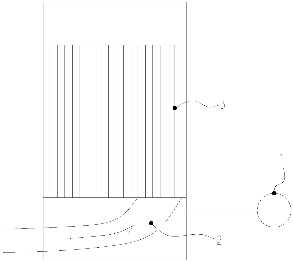
[0030] Such as figure 1 As shown, a wind equalizing device at least includes a cavity 4, and the flue gas 2 enters through the entrance of the cavity 4, and flows from the cavity 4 into the electrostatic field 3; wherein, the flow area of ​​the entrance of the cavity 4 is larger than The smoke circulation area of ​​the electrostatic field 3. In the present invention, through the above-mentioned settings, when the smoke 2 flowing into the cavity 4 intends to enter the electrostatic field 3, due to the reduction of the flow area, there will be short-term storage and collision. The occurrence of...


PUM


Abstract

Belonging to the technical field of dust removers, the invention specifically relates to a flow gas equilibrating device applicable to dust removers. The flow gas equilibrating device at least comprises a cavity, flue gas enters the cavity through a cavity inlet, and circulates into an electrostatic field from the cavity. Specifically, the inlet circulation area of the cavity is larger than the flue gas circulation area of the electrostatic field. According to the invention, through the arrangement, transient accumulation and collision can occur to the flue gas flowing into the cavity while the flue gas tries to enter the electrostatic field due to decrease of the circulation area, the situation can enable quick and uniform mixing of the flue gas in the cavity, specifically, congestion canoccur to electrostatic channels in which a lot of flue gas circulates originally, and the congestion can cause conveying of redundant flue gas to electrostatic channels with little flow volume originally, so that the actual circulation area in the electrostatic field can be the designed circulation area, the flow rate and dust removal time can be set according to the requirements, and the dust removal effect can be guaranteed.

Description

technical field [0001] The invention belongs to the technical field of dust collectors, and in particular relates to an air flow equalization device applied to dust collectors. Background technique [0002] Such as figure 1 As shown, the current dust remover provides power for the flue gas 2 to flow through the power device 1 during use, so that the flue gas passes through the electrostatic field 3 to perform dust removal operations. However, in the current use process, because the smoke 2 does not have any flow equalization device before entering the electrostatic field 3, the smoke 2 will be attracted by the power device 1 to one side of the electrostatic field 3, thereby entering the electrostatic field 3 Dust removal is carried out in a relatively concentrated area in the middle, which will cause the following problems: the reduction of the actual flow area in the electrostatic field 3 relative to the design flow area will cause the increase of the flow rate of the flue...

Claims


Application Information

Patent Timeline
Patent Type & Authority Applications(China)
IPC IPC(8): B03C3/36
CPCB03C3/363
Inventor 冯玉报朱佳泽吴晨李修明其他发明人请求不公开姓名
Owner 江苏蓝博环保机械有限公司
Why Eureka
Try Eureka