
Clamping workbench for building steel pipe machining

A workbench and steel pipe technology, applied in metal processing equipment, metal processing machinery parts, clamping, etc., can solve the problems affecting the processing accuracy of steel pipes, the steel pipes are prone to slipping, and the practicability is not strong, so as to achieve reasonable structure and novel design , the effect of simple operation

Inactive Publication Date: 2018-11-16
周国京
View PDF10 Cites 19 Cited by
  • Summary
  • Abstract
  • Description
  • Claims
  • Application Information

AI Technical Summary

Problems solved by technology

[0004] At present, construction steel pipes are widely used in practical use. Generally, the processing of construction steel pipes is mainly cutting or drilling. In order to ensure the accuracy of construction steel pipe processing, we need to fix and clamp the steel pipes in the actual processing process. However, the existing construction steel pipe clamping table often loosens during the practical process, making the steel pipe prone to slipping during the processing process, which seriously affects the post-processing accuracy of the steel pipe. , not very practical

Method used


Image

  • Clamping workbench for building steel pipe machining
  • Clamping workbench for building steel pipe machining
  • Clamping workbench for building steel pipe machining

Examples


Embodiment Construction

[0025] It should be noted that, in the case of no conflict, the embodiments of the present invention and the features in the embodiments can be combined with each other.

[0026] In describing the present invention, it should be understood that the terms "center", "longitudinal", "transverse", "upper", "lower", "front", "rear", "left", "right", " The orientations or positional relationships indicated by "vertical", "horizontal", "top", "bottom", "inner" and "outer" are based on the orientations or positional relationships shown in the drawings, and are only for the convenience of describing the present invention and Simplified descriptions, rather than indicating or implying that the device or element referred to must have a particular orientation, be constructed and operate in a particular orientation, and thus should not be construed as limiting the invention. In addition, the terms "first", "second", etc. are used for descriptive purposes only, and should not be understood ...


PUM


Abstract

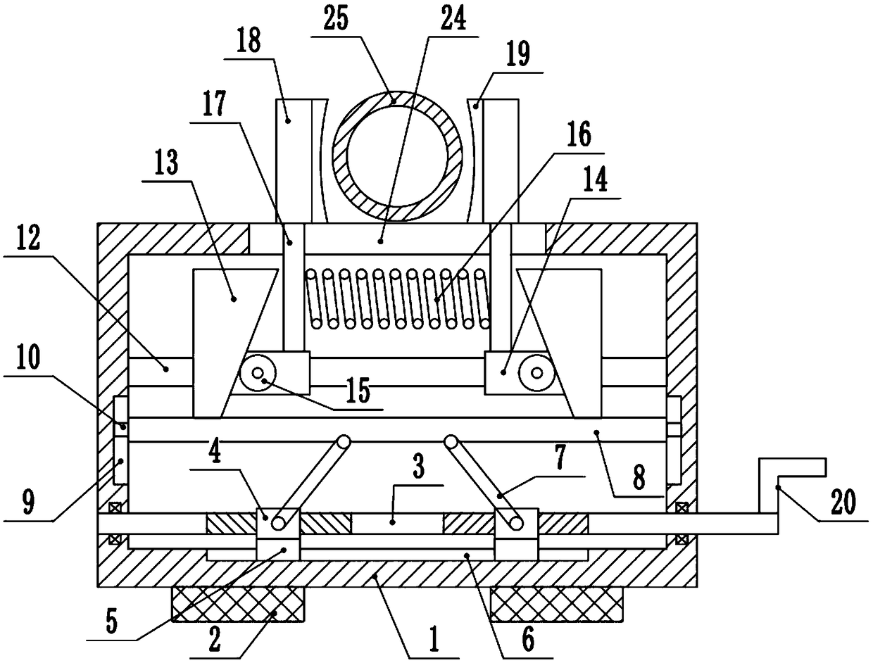
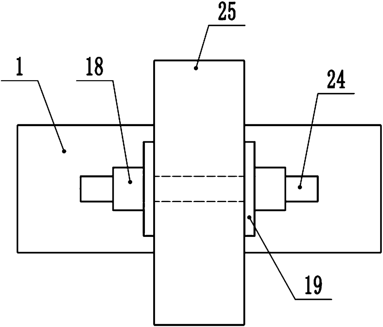
The invention discloses a clamping workbench for building steel pipe machining. The clamping workbench comprises a fixing box. A rotation rod is arranged at the bottom end in the fixing box. Movable blocks are arranged at the middle portions of the two ends of the rotation rod. Limiting blocks are arranged at the lower ends of the movable blocks. A guiding rod is arranged at the upper end in the fixing box. A left-hand thread is arranged at the middle portion of the left end of the rotation rod. A right-hand thread is arranged at the middle portion of the right end of the rotation rod. A lifting plate is hinged to the upper ends of the movable blocks through hinge rods. Wedge blocks are fixed to the two sides of the upper end of the lifting plate. Guide sleeves are arranged at the middle portions of the two ends of the guiding rod. Guiding balls are arranged at the middle portions of the front ends of the guiding sleeves. Clamping rods are arranged at the middle portions of the upper ends of the guiding sleeves, and the upper ends of the clamping rods penetrate guiding grooves and are connected with clamping blocks. According to the clamping workbench for building steel pipe machining, the clamping rods move in the opposite directions, the clamping function of a to-be-machined steel pipe is achieved through the self-locking function of the wedge blocks, and various machining needs of the building steel pipe are met; and the whole process is simple in operation, and reliability is high.

Description

technical field [0001] The invention relates to the technical field of construction machinery and equipment, in particular to a clamping workbench for processing construction steel pipes. Background technique [0002] Architecture is the general term for buildings and structures, and it is an artificial environment created by people using the material and technological means they have mastered, and using certain scientific laws, feng shui concepts, and aesthetic principles to meet the needs of social life. [0003] Steel pipes for construction can be divided into seamless steel pipes and seamed steel pipes according to the seamlessness of seams. Seamed steel pipes are divided into spiral steel pipes and straight seam steel pipes according to the different welds. The two are widely used in construction piling, structure, steel structure, load-bearing, drainage and other aspects. The main materials are carbon steel, stainless steel, alloy steel. Among them, carbon steel is t...

Claims


Application Information

Patent Timeline
Patent Type & Authority Applications(China)
IPC IPC(8): B23Q3/06
CPCB23Q3/064
Inventor 周国京
Owner 周国京
Learn More