
Pipe mouth pressure automatic regulating structure

An automatic adjustment and nozzle technology, applied in the direction of engine components, safety valves, balance valves, etc., can solve the problems of complex pressure relief structure and poor pressure relief effect, and achieve simple structure, good marketability, and good practicability Effect

Inactive Publication Date: 2018-11-16
四川丞味商贸有限公司
View PDF0 Cites 2 Cited by
  • Summary
  • Abstract
  • Description
  • Claims
  • Application Information

AI Technical Summary

Problems solved by technology

[0002] In some pressure vessels, there are usually pressure relief devices to ensure the safe operation of the pressure vessels, but the existing pressure relief devices and structures are often complicated and the pressure relief effect is not good, so it is necessary to develop a Good pressure relief structure

Method used


Image

  • Pipe mouth pressure automatic regulating structure

Examples


Embodiment Construction

[0010] The embodiments of the present invention will be further described below in conjunction with the accompanying drawings.

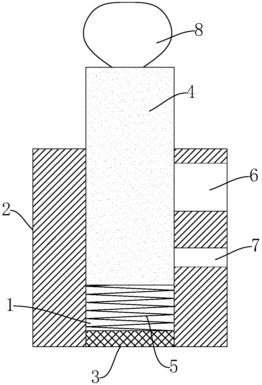
[0011] Such as figure 1 As shown, a nozzle pressure automatic adjustment structure provided in this embodiment includes a nozzle 2 provided with an exhaust hole 1, and an air intake plate 3 is fixedly provided at the bottom of the exhaust hole 1, and the air intake plate 3 It is a mesh structure, and the exhaust hole 1 is provided with a matching blocking column 4, and a spring 5 is arranged between the blocking column 4 and the air intake plate 3, and one end of the spring 5 is connected to the air intake plate 3. Fixedly connected, the other end is fixedly connected with the blocking column 4.

[0012] A first pressure relief hole 6 and a second pressure relief hole 7 communicating with the exhaust hole 1 are horizontally provided on the side wall of the nozzle 2, the first pressure relief hole 6 is located above the second pressure relief hole 7,...


PUM


Abstract

The invention particularly relates to a pipe mouth pressure automatic regulating structure. The structure comprises a pipe mouth provided with an exhaust hole. An air inlet plate is fixedly arranged at the bottom of the exhaust hole and is of a netty structure. A well-matched plug column is arranged in the exhaust hole. A spring is arranged between the plug column and the air inlet plate. One endof the spring is fixedly connected with the air inlet plate, and the other end of the spring is fixedly connected with the plug column. A first pressure release hole and a second pressure release holewhich communicate with the exhaust hole are transversely formed in the side wall of a pipe mouth. The first pressure release hole is located above the second pressure release hole. According to the structure, pressure releasing operation can be achieved, the pressure releasing amount is automatically regulated according to the pressure, and meanwhile, the structure is simple in structure, ingenious in design and quite good in practicability and market popularization.

Description

technical field [0001] The invention specifically relates to a nozzle pressure automatic adjustment structure. Background technique [0002] In some pressure vessels, there are usually pressure relief devices to ensure the safe operation of the pressure vessels, but the existing pressure relief devices and structures are often complicated and the pressure relief effect is not good, so it is necessary to develop a Pressure relief structure with good pressure relief effect. Contents of the invention [0003] The purpose of the present invention is to provide a structure with simple structure and ingeniously designed nozzle pressure automatic adjustment structure. [0004] The technical solution adopted in the present invention is: an automatic nozzle pressure adjustment structure, including a nozzle with a vent hole, an air intake plate is fixed at the bottom of the vent hole, and the air intake plate is a mesh structure. A matching plugging post is provided in the exhaust...

Claims


Application Information

Patent Timeline
IPC IPC(8): F16K17/04
CPCF16K17/046F16K17/0486
Inventor 伍俊辉
Owner 四川丞味商贸有限公司
Learn More