Display device

A technology of a display device and a display panel, which is applied in the electronic field, can solve problems such as uneven display brightness of a display device, and achieve the effects of improving user experience, expanding the display area, and increasing the light emission rate

Active Publication Date: 2018-11-16
XIAMEN TIANMA MICRO ELECTRONICS
View PDF3 Cites 14 Cited by
  • Summary
  • Abstract
  • Description
  • Claims
  • Application Information

AI Technical Summary

Problems solved by technology

[0003] An embodiment of the present invention provides a display device, which is used to solve the technical problem of uneven display brightness of the display device in the prior art

Method used


Image

  • Display device
  • Display device
  • Display device

Examples


Embodiment Construction

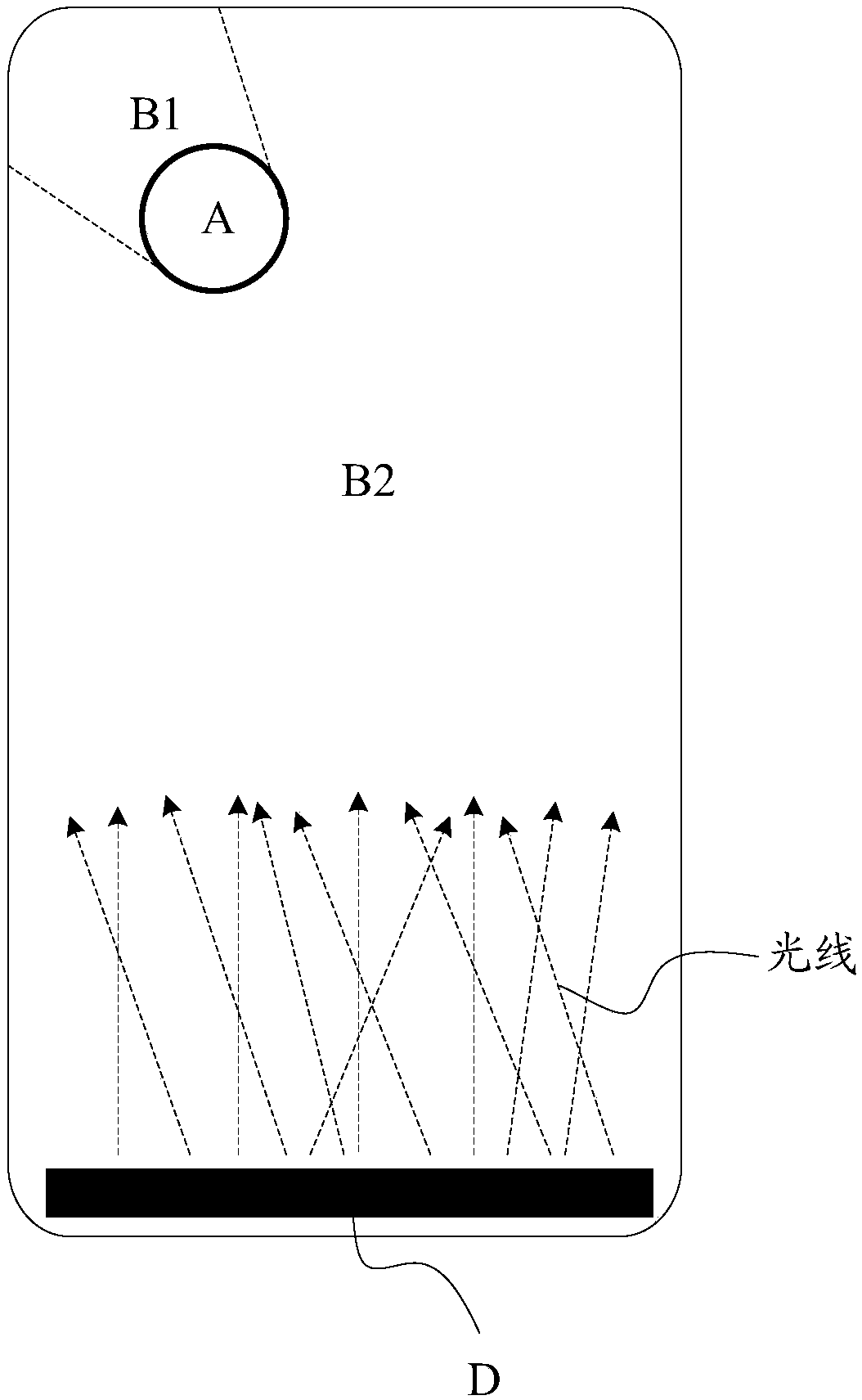
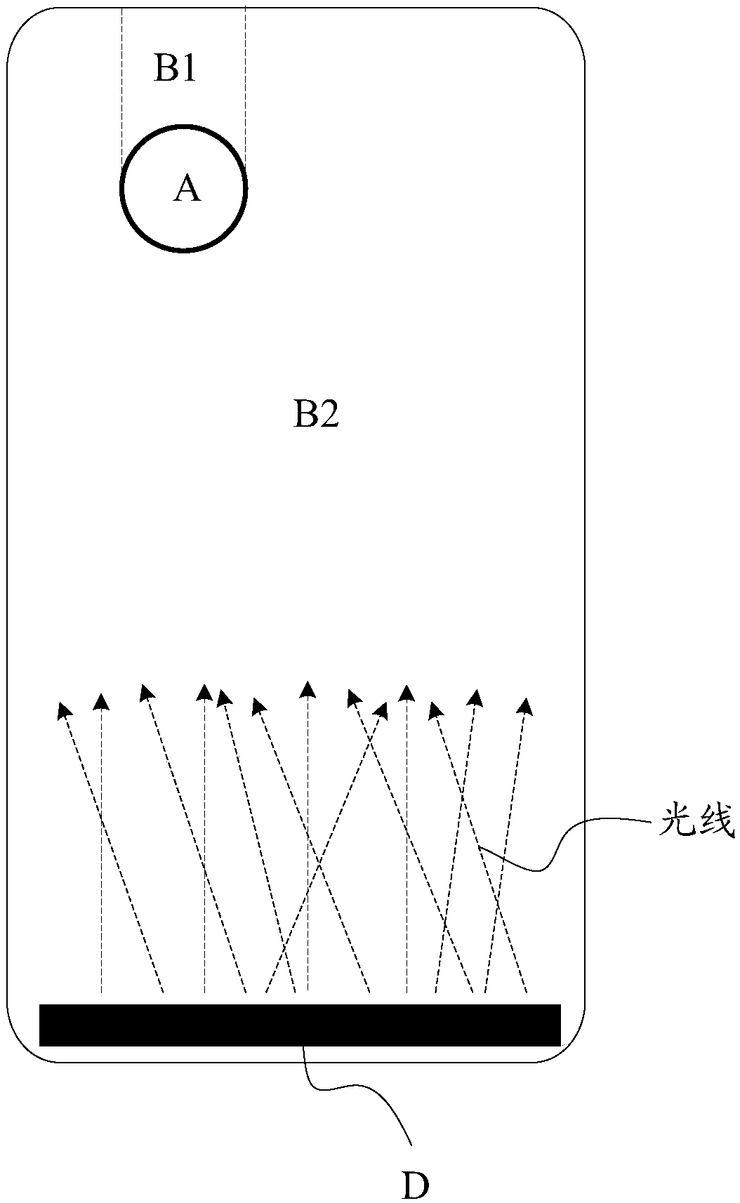
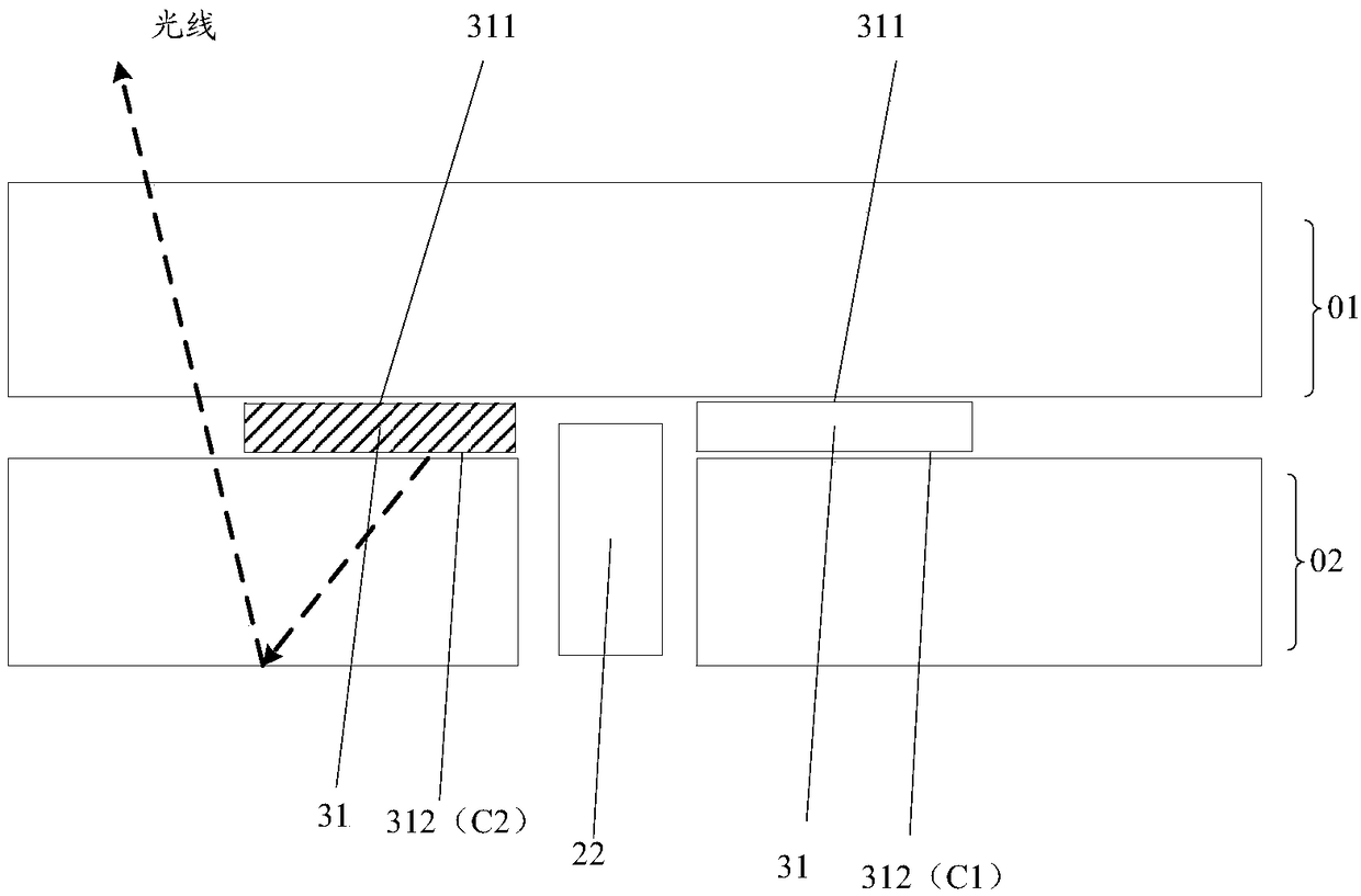
[0051] In order to make the object, technical solution and advantages of the present invention clearer, the specific implementation manner of the display device provided by the embodiment of the present invention will be described in detail below with reference to the accompanying drawings. It should be understood that the preferred embodiments described below are only used to illustrate and explain the present invention, not to limit the present invention. And in the case of no conflict, the embodiments in the present application and the features in the embodiments can be combined with each other.

[0052] It should be understood that in the description of the embodiments of the present invention, words such as "first" and "second" are only used to distinguish the purpose of description, and cannot be understood as indicating or implying relative importance, nor can they be understood as indicating or imply order. "Multiple" in the description of the embodiments of the prese...


PUM


Abstract

The invention provides a display device. The display device comprises a display panel and a backlight module opposite to the display panel, wherein the backlight module comprises a lateral light source; the backlight module is provided with a through hole, which penetrates through the backlight module and are used for mounting functional modules. The display device also comprises a first masking tape which is arranged around the through hole and on the light-emitting surface of the backlight module for fixing the display panel and the backlight module; the first masking tape comprises a blackfirst surface adhered to the display panel, and a second surface adhered to the backlight module, wherein the second surface comprises a black first area and a white second area, the first area is arranged on the side of the through hole which is close to the lateral light source, and the second area is arranged on the side of the through hole which is away from the lateral light source.

Description

technical field [0001] The present invention relates to the field of electronic technology, in particular to a display device. Background technique [0002] In existing display devices such as mobile phones and tablet computers, in order to expand the display area as much as possible, such as figure 1 or figure 2 As shown, holes will be dug in area A of the display area to place cameras, speakers and other devices in the holes. However, due to the existence of the hole, the path of the light emitted by the light source in the backlight module to the display area B1 on the side of the hole away from the light source is blocked, causing the light entering the side of the hole away from the light source to extend to the backlight module along the direction away from the light source. The display area B1 at the edge of the group has little light, and the brightness of the display area B1 is darker than the brightness of the display area B2 extending from the side of the hole ...

Claims


Application Information

Patent Timeline
Patent Type & Authority Applications(China)
IPC IPC(8): F21S8/00F21V7/04G09F9/00
CPCF21S8/00F21V7/04G09F9/00
Inventor 刘广平朱志强柯耀作王小龙
Owner XIAMEN TIANMA MICRO ELECTRONICS
Why Eureka
Try Eureka