Method for detecting looseness of rail splice fastener
A detection method and fastener technology, applied in image data processing, instruments, calculations, etc., can solve problems such as loosening, reducing the connection and fixing effect of two rails, affecting the safety of track operation, and achieving the effect of ensuring safety
- Summary
- Abstract
- Description
- Claims
- Application Information
AI Technical Summary
Problems solved by technology
Method used
Image
Examples
Embodiment 1
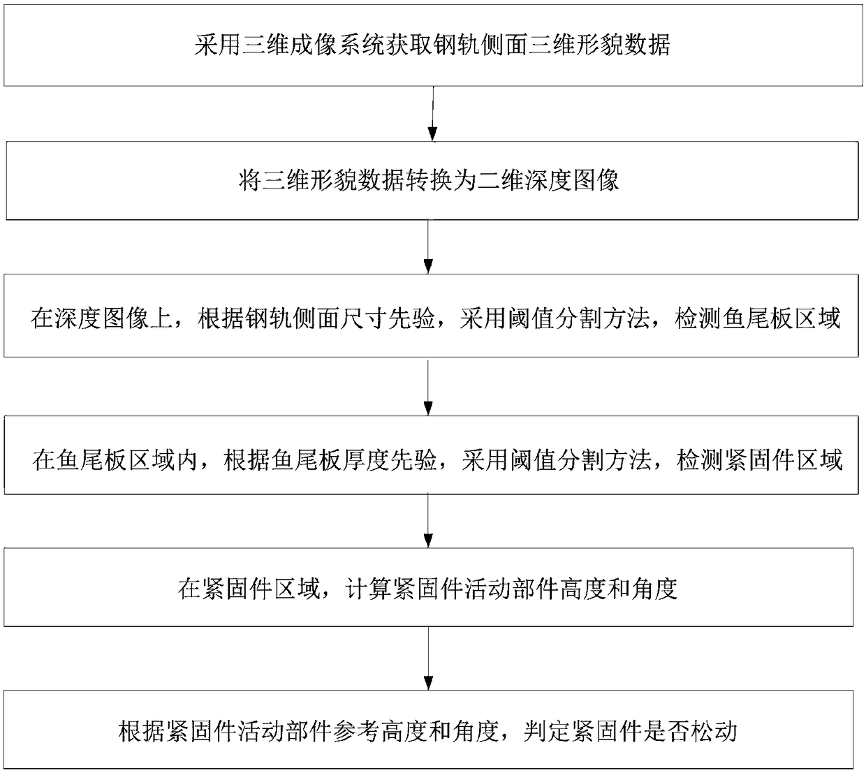
[0048] A method for detecting looseness of rail fishplate fasteners, specifically as follows:
[0049] Step 1: Use the 3D imaging system to obtain the 3D topography data of the rail side.
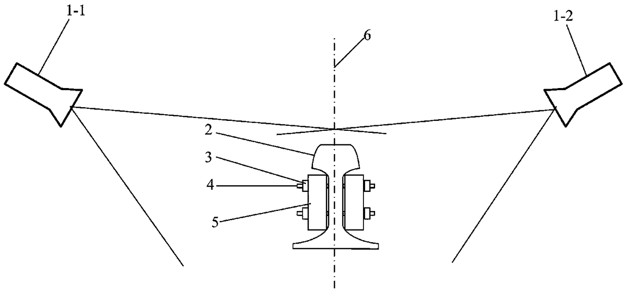
[0050] Such as figure 2 As shown, two sets of 3D imaging systems 1 are used to perform 3D imaging of the areas on both sides of the rail 2 to obtain structural 3D topography data including the rail 2, fishplate 5, nut 3, and screw 4. The 3D imaging system here is a line-structured 3D scanning system.
[0051] Step 2: If figure 2 As shown, take the vertical plane perpendicular to the track plane and parallel to the track direction as the horizontal reference plane 6 of the depth image, and convert the three-dimensional topography data into a two-dimensional depth image; the bit width of the two-dimensional depth image is 8 bits, and the unit pixel value The height resolution is 0.1mm.
[0052] Step 3: On the two-dimensional depth image, according to the size information of the rail sid...
Embodiment 2
[0070] The difference from Example 1 is that in step a-5-7, the black and white pattern of a regular polygon whose circumcircle radius is r3 is used as a template T, the white area is a regular polygon, and the black area is a background, with C(x c ,y c ) is a dot, set the angle search range of -k1~k1 degrees, and the search step is k2 degrees, compare the similarity between the area G and the template T, find the most similar angle, and use it as the nut angle β c , the value range of k1 is 0-120 degrees, and the value range of k2 is 0-60 degrees.
Embodiment 3
[0072] The difference with embodiment 1 is that the height h of the nut 3 is calculated in step 5 c The method is:
[0073] Step b-5-1: Perform threshold segmentation on the depth pixels in the fastener area to obtain the area R:
[0074]
[0075] Among them, f(x,y) represents the gray value of the depth image pixel at (x,y) in the fastener area, v max is the maximum gray value of the depth image pixel in the fastener area, a=10;
[0076] Step b-5-2: Perform morphological filtering on the region R to eliminate isolated noise, calculate the circumcircle radius r5 of the region R, and when r5>r2+e2, calculate the average or median value of the pixels in the region R as the nut height h c , otherwise go to step b-5-3;
[0077] Step b-5-3: Carry out circular fitting on the region R, take the center of the circle as the center, set concentric rings with radii r6 and r7, r6=r2+e3, r7=r3-e3, in Take the average or median value of the pixels in the ring area on the depth image...
PUM
 Abstract
Description
Claims
Application Information
 - R&D
- Intellectual Property
- Life Sciences
- Materials
- Tech Scout
- Unparalleled Data Quality
- Higher Quality Content
- 60% Fewer Hallucinations
Browse by: Latest US Patents, China's latest patents, Technical Efficacy Thesaurus, Application Domain, Technology Topic, Popular Technical Reports.
© 2025 PatSnap. All rights reserved.Legal|Privacy policy|Modern Slavery Act Transparency Statement|Sitemap|About US| Contact US: help@patsnap.com


