A kind of manufacturing method of bn ion gate and manufacturing substrate

A manufacturing method and ion gate technology, which are used in the manufacture of electronic/ion optical devices, particle separation tubes, and non-light-emitting electrodes, can solve the problems of long assembly time, complex manufacturing process, harsh manufacturing conditions, etc., and achieve batch processing. Effect

Active Publication Date: 2019-11-26
SHENZHEN GRADUATE SCHOOL TSINGHUA UNIV
View PDF6 Cites 0 Cited by
  • Summary
  • Abstract
  • Description
  • Claims
  • Application Information

AI Technical Summary

Problems solved by technology

The U.S. patent with the patent publication number US7358593B2 invented a method for making miniature ion gates using Deep Reactive Ion Etching (DRIE) technology. hours days
These methods can produce high-quality ion gates, but the manufacturing process is complicated, the cost is high, and the assembly time is long; and because the Young's modulus of the insulating substrate is much smaller than that of the metal wire, under the same stress conditions, the substrate cannot Inconsistent with the deformation of the metal wire, the BN ion gate produced by these methods still has the problem of uneven radial electric field and instability, which affects the performance of the BN ion gate to a certain extent, so the existing BN ion gate still continues to improve the quality objective needs

Method used


Image

  • A kind of manufacturing method of bn ion gate and manufacturing substrate
  • A kind of manufacturing method of bn ion gate and manufacturing substrate
  • A kind of manufacturing method of bn ion gate and manufacturing substrate

Examples


Embodiment

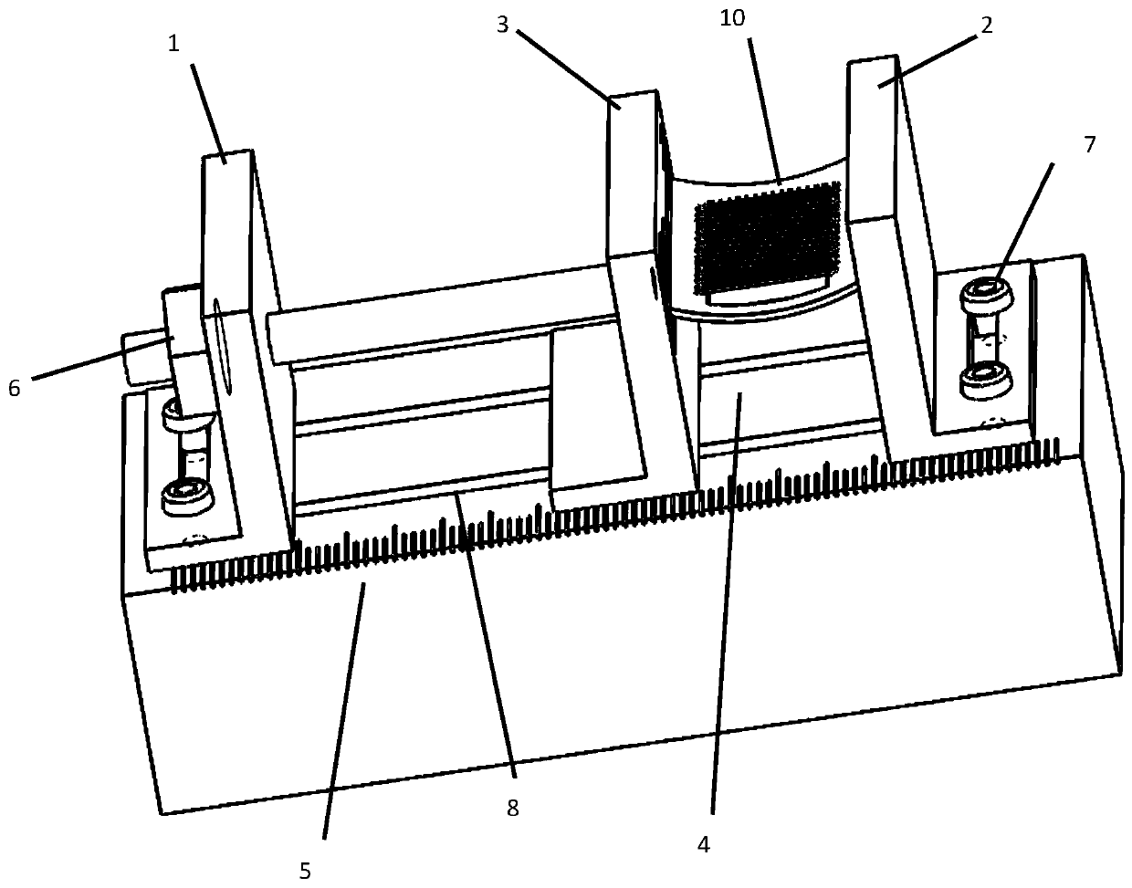
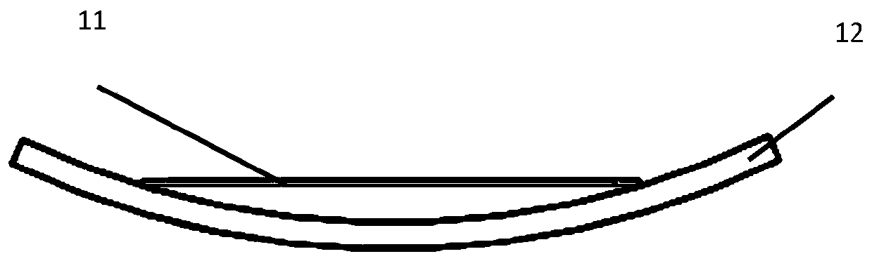
[0018] figure 1 It is a schematic diagram of the insulating substrate of this embodiment when the metal wire is bent and fixed on the jig, figure 2 is a schematic diagram of a curved BN ion gate, image 3 It is a schematic diagram after straightening. Wherein the fixture has a first fixed block 1, a second fixed block 2, a sliding block 3, a third fixed block 4, a scale 5, a positioning screw 6, a positioning screw 7, and a fixing groove 8.

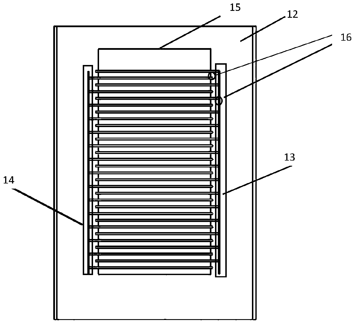
[0019] 10 of them are BN ion gates in production, such as figure 2 , 3 As shown, it includes a substrate 12 and a wire 11 .

[0020] Figure 4 Shown in the bottom surface of the groove 31 sliding feet 32 ​​for fixing the sliding block 3 of the curved ion gate.

[0021] The substrate 12 is a PCB board with a thickness of 0.8 mm to 1.6 mm, the outer frame is a square frame, and the center is a rectangular through hole 15 . Two sets of mutually insulated first copper-clad regions 13 and second copper-clad regions 14 are distributed ...


PUM


Abstract

A BN ion gate manufacturing method and a manufacturing substrate are disclosed. That method comprises the following steps: providing an insulating substrate and a metal wire; providing a fixture to act on the insulating substrate, so as to bend the insulating substrate on the jig, so as to form a plurality of wire segments arranged parallel to each other and equally spaced on the curved concave surface of the insulating substrate, and a plurality of the metal wire segments form a first metal wire group and a second metal wire group which are alternately arranged and insulated from each other,and when the bent insulating substrate is released, each of the metal wire segments forms a straight line with a tensioning force which is relatively tight due to bending tension. The radial electricfield of the BN ion gate manufactured by the method of the invention is uniform and stable.

Description

technical field [0001] The present invention relates to a kind of device for controlling ions, particularly relate to a kind of BN ion gate (BN type ion gate, is the device that can be used for controlling ions in time-of-flight mass spectrometry and ion mobility spectrometry. The device is based on changing local The electric field is used to change the ion flight trajectory, and to deflect or block the ion flow) The production method and the fixed fixture. Background technique [0002] An ion gate is a device that controls the movement of ions in instruments such as ion mobility spectrometry, time-of-flight mass spectrometry, and electron microscopy. By applying a potential difference between two sets of metal wires that are alternately arranged in parallel, a deflection or blocking electric field perpendicular to the original motion direction of ions is formed, which can deflect the trajectory of ions or block ions. [0003] A variety of ion gate types for controlling io...

Claims


Application Information

Patent Timeline
Patent Type & Authority Patents(China)
IPC IPC(8): H01J49/06H01J9/14
CPCH01J9/14H01J49/061
Inventor 余泉李坤晓王晓浩钱翔倪凯
Owner SHENZHEN GRADUATE SCHOOL TSINGHUA UNIV
Why Eureka
Try Eureka