
System and method for remote monitoring of long-distance conveying pipeline

A transmission pipeline and remote monitoring technology, applied in transmission systems, radio transmission systems, measuring devices, etc., can solve problems such as difficult to find problems in time, multiple cross-regions, pollution, etc., and achieve the effect of improving safety

Inactive Publication Date: 2018-11-16
BEIJING GUODIAN GAOKE TECH CO LTD
View PDF0 Cites 4 Cited by
  • Summary
  • Abstract
  • Description
  • Claims
  • Application Information

AI Technical Summary

Problems solved by technology

[0002] Oil, natural gas and other energy sources play a very important role in economic development. After mining and processing, this type of energy needs to be transported to distant places for use through pipelines or gas pipelines; because oil pipelines and gas pipelines span The distance is relatively long, and in order to avoid affecting people’s daily life, oil pipelines and gas pipelines are usually laid in relatively remote places; various failures may occur in oil pipelines or gas pipelines during use, such as Damage due to corrosion, aging and oil theft will lead to oil and gas leakage, which may cause fire and environmental pollution. Therefore, it is very important to monitor the condition and leak detection of the pipeline
[0003] In the prior art, the monitoring and leak detection of oil pipelines and gas pipelines all adopt the method of manual regular patrol inspection. Due to the long laying distance of the pipeline, many cross-regions, complex geology and natural environment along the way, manual patrol inspection is very difficult. The inspection is difficult to a certain extent, which makes it difficult to find problems in time and take corresponding maintenance measures

Method used


Image

  • System and method for remote monitoring of long-distance conveying pipeline
  • System and method for remote monitoring of long-distance conveying pipeline
  • System and method for remote monitoring of long-distance conveying pipeline

Examples


Embodiment Construction

[0030] In order to make the purpose, technical solutions and advantages of the embodiments of the present invention clearer, the technical solutions in the embodiments of the present invention will be clearly and completely described below in conjunction with the drawings in the embodiments of the present invention. Obviously, the described embodiments are only It is a part of embodiments of the present invention, but not all embodiments. The components of the embodiments of the invention generally described and illustrated in the figures herein may be arranged and designed in a variety of different configurations. Accordingly, the following detailed description of the embodiments of the invention provided in the accompanying drawings is not intended to limit the scope of the claimed invention, but merely represents selected embodiments of the invention. Based on the embodiments of the present invention, all other embodiments obtained by those skilled in the art without making...


PUM


Abstract

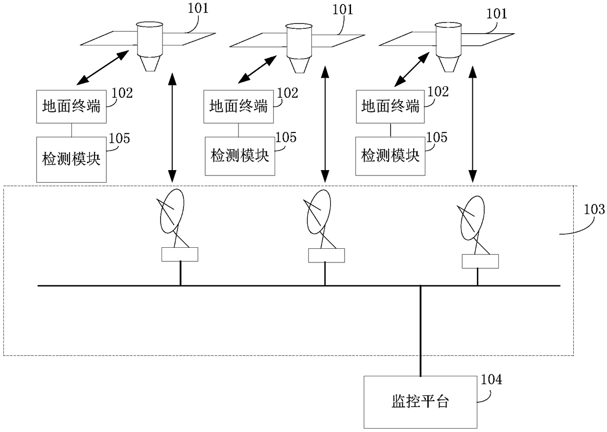
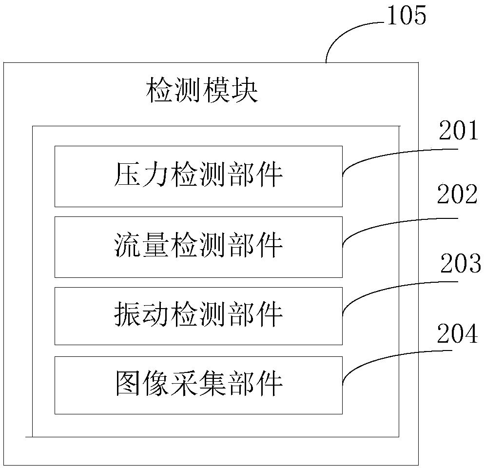
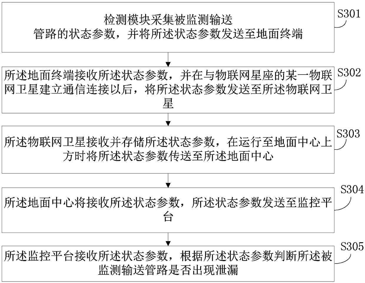
The invention provides a system and a method for remote monitoring of a long-distance conveying pipeline. The system comprises a detection module, a data transmission module and a monitoring platform;wherein the data transmission module comprises a ground terminal, an IoT (Internet of Things) constellation consisting of a plurality of IoT satellites, and a ground center; the detection module is used for acquiring a state parameter of a monitored conveying pipeline, and transmitting the state parameter to the ground terminal; the ground terminal is used for receiving the state parameter, and transmitting the state parameter to the IoT satellites; the IoT satellites are used for receiving and storing the state parameter, and transmitting the state parameter to the ground center when runningto a position over the ground center; the ground center is used for transmitting the state parameter to the monitoring platform, and the monitoring platform is used for judging whether a leakage condition occurs on the monitored conveying pipeline according to the state parameter. The system and the method of the invention are capable of achieving remote monitoring of the long-distance conveyingpipeline.

Description

technical field [0001] The invention relates to the technical field of pipeline transportation, in particular to a remote monitoring system and method for long-distance transportation pipelines. Background technique [0002] Oil, natural gas and other energy sources play a very important role in economic development. After mining and processing, this type of energy needs to be transported to distant places for use through pipelines or gas pipelines; because oil pipelines and gas pipelines span The distance is relatively long, and in order to avoid affecting people's daily life, oil pipelines and gas pipelines are usually laid in relatively remote places; various failures may occur in oil pipelines or gas pipelines during use, such as Damage due to corrosion, aging and oil theft will lead to oil and gas leakage, which may cause fire and environmental pollution. Therefore, it is very important to monitor the condition and leak detection of the pipeline. [0003] In the prior ...

Claims


Application Information

Patent Timeline
Patent Type & Authority Applications(China)
IPC IPC(8): H04L29/08H04W4/38H04B7/185G01D21/02
CPCH04L67/12G01D21/02H04B7/1851H04W4/38
Inventor 刘涛吕强张进武王淼郭中甲朱莲芝马萍苗楚南唐尧宋博李云鹏单黎明刘千玉贾娇
Owner BEIJING GUODIAN GAOKE TECH CO LTD
Learn More