

Auxiliary device for displaying cnc teaching cutters
A technology of auxiliary devices and knives, which is applied in the field of learning tools, can solve the problems of not helping students to observe, reducing students' learning efficiency, and inconvenient display of knives, so as to achieve the effects of reducing fixed time, fast and convenient fixing, and improving efficiency
- Summary
- Abstract
- Description
- Claims
- Application Information
AI Technical Summary
Problems solved by technology
Method used
Image

Examples
Embodiment Construction
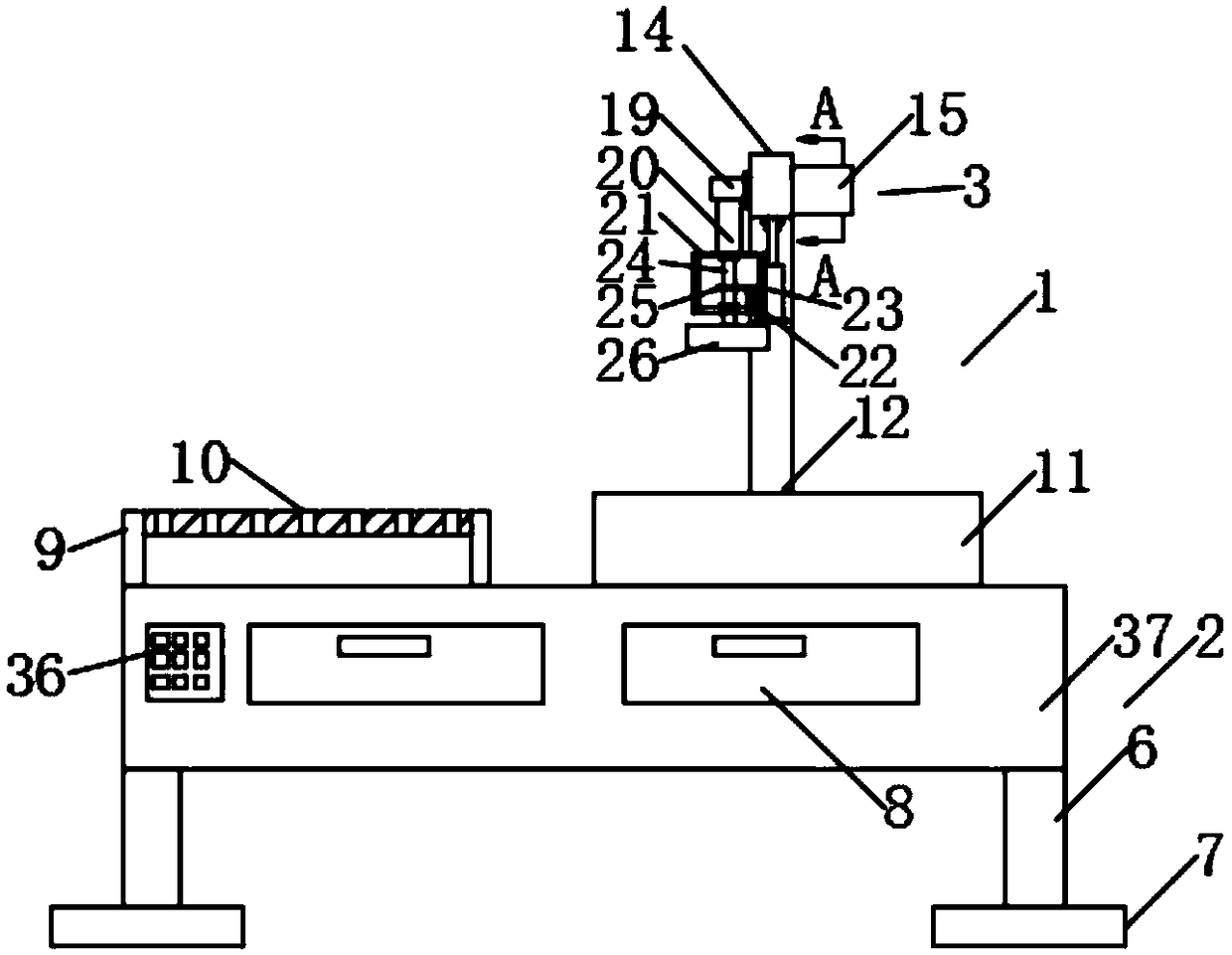
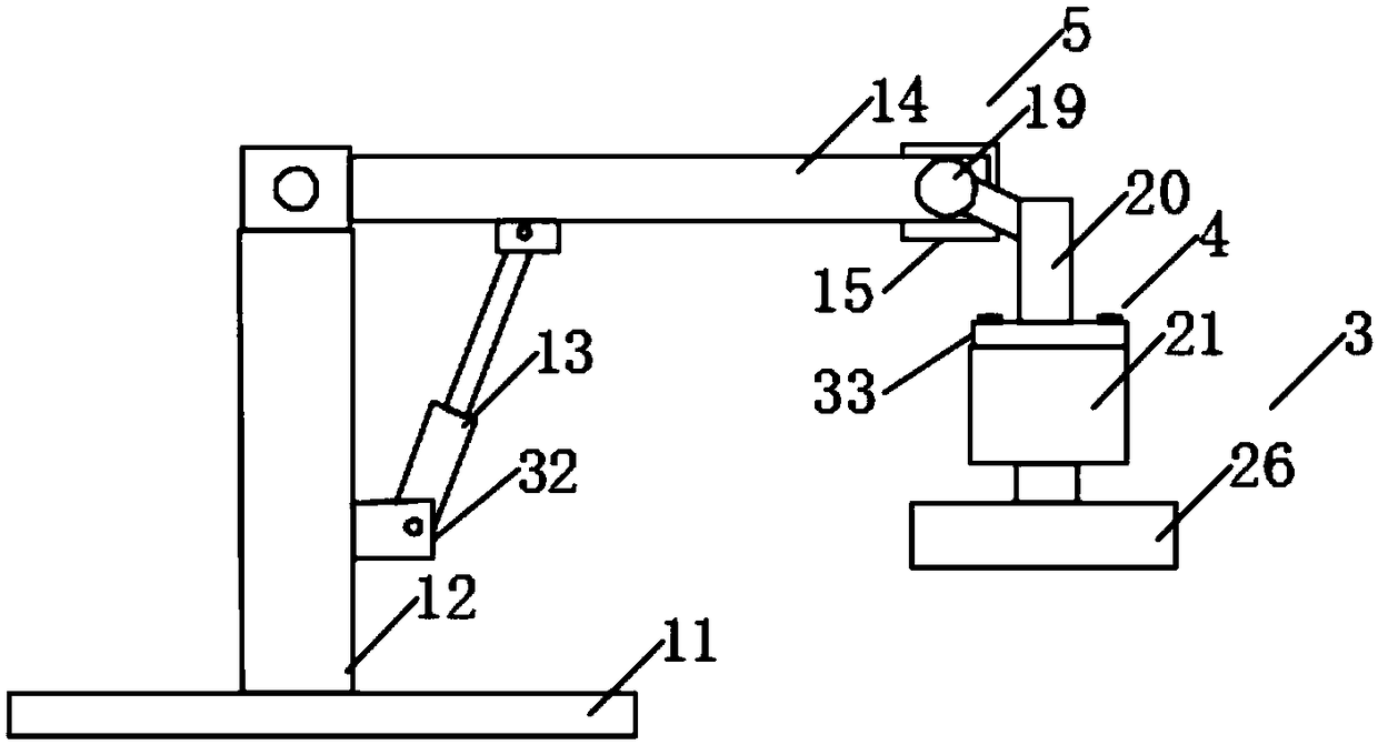
[0022] Such as Figure 1-6 As shown, the specific embodiment adopts the following technical solutions: an auxiliary device for cnc teaching tool display, including an auxiliary device body 1, and the auxiliary device body 1 is composed of a fixing mechanism 2, a supporting mechanism 3, a rotating mechanism 5 and a display mechanism 4, the top of the fixing mechanism 2 is fixedly connected with a supporting mechanism 3, one end of the supporting mechanism 3 rotates the rotating mechanism 5, and one end of the rotating mechanism 5 fixes the display mechanism 4, and the fixing mechanism 2 consists of a storage box 37 , a pillar 6, a support plate 7 and a storage drawer 8. The four corners of the bottom of the storage box 37 are equidistantly fixedly connected with four pillars 6, and the bottom of the pillar 6 is fixedly connected with a support plate 7. One side of box 37 tops is fixedly connected with placement frame 9, and the top equidistant of described placement frame 9 is ...
PUM
 Abstract
Description
Claims
Application Information