Eureka AIR delivers breakthrough ideas for toughest innovation challenges, trusted by R&D personnel around the world.

Side-lying auxiliary device for CT inspection and puncture

An auxiliary device and piercing technology, which is applied in the fields of application, radiological diagnostic equipment, medical science, etc., can solve the problems of patients' physical fatigue, easy fatigue, and difficulty in maintaining the side lying position for a long time, and achieve good effect and use The effect of convenience and simple structure

Pending Publication Date: 2018-11-20
PEKING UNIV SHENZHEN HOSPITAL
View PDF5 Cites 3 Cited by
  • Summary
  • Abstract
  • Description
  • Claims
  • Application Information

AI Technical Summary

Problems solved by technology

[0004] At present, when patients undergo CT detection and treatment, they generally maintain a lying position. However, for some special patients, such as disabled patients, they need to maintain a lateral position in order to achieve better inspection results. However, due to the physical Instinctive reaction, the human body cannot lie on the side for a long time, which will cause physical fatigue of the patient and affect the good effect of CT examination and treatment
[0005] In addition, for patients treated by CT puncture, multiple body position adjustments are required during the puncture process. Therefore, when maintaining the lateral position, there are also problems such as easy fatigue and difficulty in maintaining the lateral position for a long time.

Method used


Image

  • Side-lying auxiliary device for CT inspection and puncture
  • Side-lying auxiliary device for CT inspection and puncture
  • Side-lying auxiliary device for CT inspection and puncture

Examples


Embodiment Construction

[0080] Embodiments of the present invention are described in detail below, examples of which are shown in the drawings, wherein the same or similar reference numerals designate the same or similar elements or elements having the same or similar functions throughout. The embodiments described below by referring to the accompanying drawings are exemplary and are intended to explain the present invention, but cannot be construed as limitations to the present invention. Based on the embodiments in the present invention, those skilled in the art do not make creative work premise All other embodiments obtained below all belong to the protection scope of the present invention.

[0081] In describing the present invention, it should be understood that the terms "center", "longitudinal", "transverse", "length", "width", "thickness", "upper", "lower", "front", " Back", "Left", "Right", "Vertical", "Horizontal", "Top", "Bottom", "Inner", "Outer", "Clockwise", "Counterclockwise", "Axial",...


PUM


Abstract

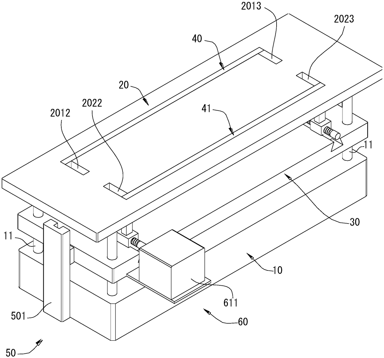
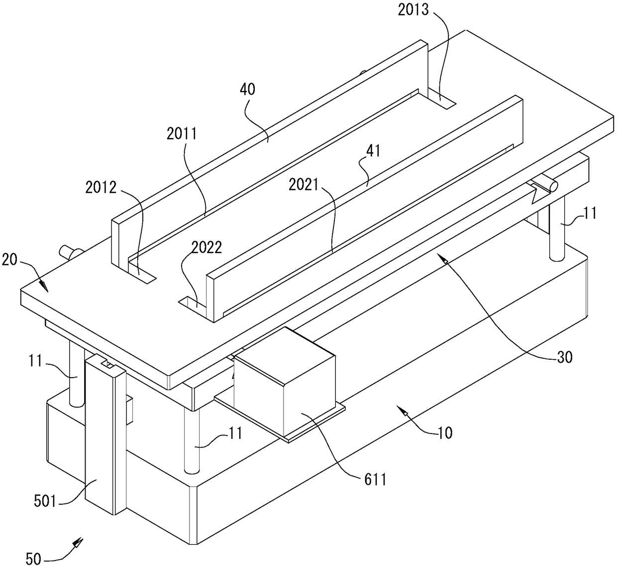
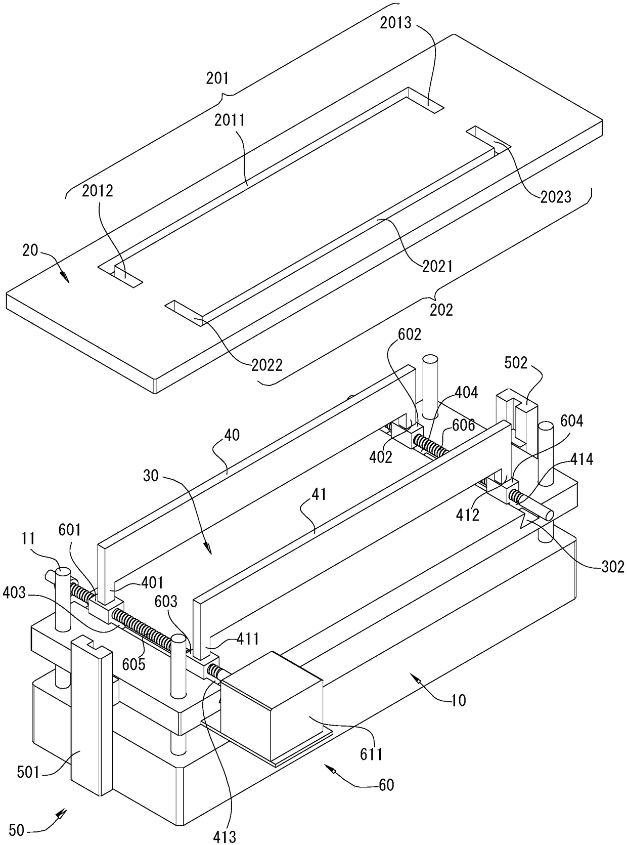
The invention discloses a side-lying auxiliary device for CT inspection and puncture. The side-lying auxiliary device comprises a base, a bed plate, a floating plate, a first splint, a second splint,a first driving mechanism and a second driving mechanism; wherein the bed plate is horizontally arranged and relatively fixed on the upper side of the base; a first through hole and a second through hole which penetrate the bed plate in the vertical direction are formed on the bed plate; the floating plate which is horizontally positioned and capable of sliding in the vertical direction is arranged between the base and the bed plate; the first splint and the second splint which are vertically positioned are relatively arranged on the floating plate and capable of relatively sliding in the width direction of a bed body; the first driving mechanism drives the floating plate to slide between a first position and a second position in the vertical direction; and the second driving mechanism drives the first splint and the second splint to move towards or against each other in opposite directions when the floating plate is located in the second position. The side-lying auxiliary device for CT inspection and puncture provided by the invention can assist a patient to keep lying on one side and ensure better effects in CT inspection and puncture, and is simple in structure and convenient for use.

Description

technical field [0001] The invention relates to the field of CT technology, in particular to a lateral assist device for CT examination and puncture. Background technique [0002] CT examination is a more advanced modern medical scanning examination technology, mainly for scanning the human brain. CT examination generally includes plain scan CT, enhanced CT and cisternal contrast CT. [0003] CT scans a layer of a certain thickness of a certain part of the human body with an X-ray beam. The X-rays that pass through this layer are received by the detector and converted into visible light, which is converted from photoelectricity into an electrical signal, and then passed through an analog / digital converter (analog / digitalconverter) into digital and input to computer for processing. [0004] At present, when patients undergo CT detection and treatment, they generally maintain a lying position. However, for some special patients, such as disabled patients, they need to maint...

Claims


Application Information

Patent Timeline
Patent Type & Authority Applications(China)
IPC IPC(8): A61B6/04A61B6/03A61B90/14A61G13/12
CPCA61B6/03A61B6/0407A61B90/14A61G13/12A61G13/1295
Inventor 黄嵘
Owner PEKING UNIV SHENZHEN HOSPITAL
Why Eureka
Eureka Blog
Learn More