Accelerator control device, accelerator control method, and particle beam therapy device

A technology for controlling devices and accelerators, used in magnetic resonance accelerators, X-ray/γ-ray/particle irradiation therapy, therapy, etc.

Active Publication Date: 2018-11-20
TOSHIBA FUEL CELL POWER SYST
View PDF5 Cites 4 Cited by
  • Summary
  • Abstract
  • Description
  • Claims
  • Application Information

AI Technical Summary

Problems solved by technology

[0003] However, immediately after the charged particle beam accelerated to a certain energy by the accelerator is emitted, a beam spike may occur in which the intensity of the charged particle beam exceeds a target value.

Method used


Image

  • Accelerator control device, accelerator control method, and particle beam therapy device
  • Accelerator control device, accelerator control method, and particle beam therapy device
  • Accelerator control device, accelerator control method, and particle beam therapy device

Examples


no. 1 Embodiment approach

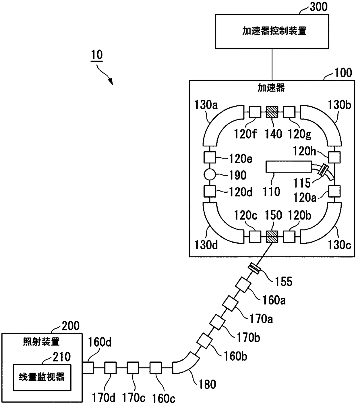
[0033] figure 1 It is a block diagram showing the overall configuration of the particle beam therapy apparatus 10 according to the first embodiment. The particle beam therapy system 10 is a device that accelerates a charged particle beam to a desired energy and irradiates an affected part such as a tumor with the accelerated charged particle beam. The particle beam therapy system 10 includes an accelerator 100 , an irradiation device 200 , and an accelerator control device 300 .

[0034] The accelerator 100 includes an injector 110 , a chopper 115 , a plurality of quadrupole electromagnets 120 a to 120 h , a plurality of deflection electromagnets 130 a to 130 d , a radio frequency acceleration cavity 140 , an injector 150 , and a current value detection unit 190 .

[0035] The injector 110 injects a charged particle beam into a orbit within the accelerator 100 . The chopper 115 is provided to adjust the amount of charged particle beam incident on the accelerator 100 .

[00...

no. 2 Embodiment approach

[0100] In the first embodiment, it is assumed that the timing control unit 310 controls the operation timing of the circuit breaker 155 for cutting off the charged particle beam emitted from the accelerator 100 . On the other hand, in the second embodiment, the timing control unit 310 controls the pulse width of the chopper pulse signal for driving the chopper 115 in addition to the control of the operation timing of the circuit breaker 155 . Hereinafter, the second embodiment will be described in detail.

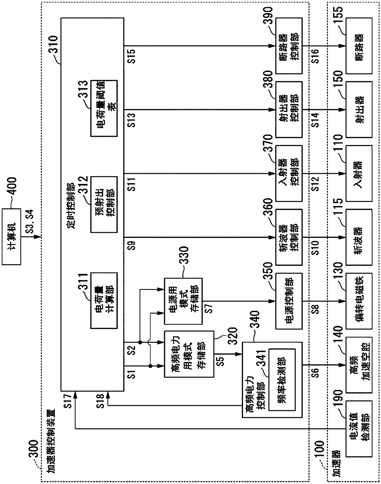
[0101] Figure 10 It is a block diagram showing the configuration of the accelerator control device 300 of the second embodiment. exist Figure 10 in, for with figure 2 The parts corresponding to the respective parts of .

[0102] The timing control unit 310 includes a pulse width control unit 314 and a pulse width threshold table 315 (second table) in addition to a charge amount calculation unit 311 , a pre-injection control unit 312 , and a charge amount threshold ta...

no. 3 Embodiment approach

[0118] The timing control unit 310 of the first embodiment and the second embodiment is configured to calculate the charge amount of the charged particle beam based on the current value of the charged particle beam circulating in the accelerator 100, and to control the charge amount based on the calculated charge amount of the charged particle beam. Operation timing of the circuit breaker 155 . In contrast, the timing control unit 310 of the third embodiment controls the operation of the circuit breaker 155 based on the current value (beam current) of the charged particle beam circulating in the accelerator 100 without calculating the charge amount of the charged particle beam. timing. Hereinafter, the third embodiment will be described in detail.

[0119] Figure 15 It is a block diagram showing the configuration of the accelerator control device 300 of the third embodiment. exist Figure 15 in, right with Figure 10 The parts corresponding to the respective parts of . ...


PUM


Abstract

Provided are: an accelerator control device, an accelerator control method, and a particle beam therapy device, by that generation of sharp peaks in wavebeam can be prevented even low-energy charged particle beam is ejected. According to some embodiments, an accelerator control device has a high-frequency power controller and a timing controller. The high-frequency power controller supplies high frequency power for accelerating a charged particle beam to an accelerator. The tinting controller controls an operation timing of a blocker that blocks the charged particle beam emitted from the accelerator based on a current value of the charged particle beam circulating in the accelerator.

Description

technical field [0001] Embodiments of the present invention relate to an accelerator control device, an accelerator control method, and a particle beam therapy device. Background technique [0002] Usually, an accelerator for accelerating a charged particle beam to a desired energy is installed in a particle beam therapy apparatus. A radio-frequency acceleration cavity with a plurality of electrodes is provided in the accelerator. A particle beam therapy apparatus supplies high-frequency power to electrodes provided in a high-frequency acceleration cavity to accelerate a charged particle beam to a desired energy, and irradiates the accelerated charged particle beam to an affected part such as a tumor. [0003] However, immediately after the charged particle beam accelerated to a certain energy by the accelerator is emitted, a beam spike may occur in which the intensity of the charged particle beam exceeds a target value. Beam spikes tend to occur especially when low energy...

Claims


Application Information

Patent Timeline
Patent Type & Authority Applications(China)
IPC IPC(8): A61N5/10
CPCA61N5/1077H05H13/04H05H2277/11A61N5/1048A61N5/1065A61N2005/1074A61N2005/1085H05H7/001A61N2005/1087A61N2005/1095H05H7/02H05H2007/022H05H2007/025
Inventor 松本宗道古川卓司水岛康太塙胜词
Owner TOSHIBA FUEL CELL POWER SYST
Why Eureka
Try Eureka