Volleyball smash training equipment

A technique for training equipment and volleyball, applied to sports accessories and other directions, can solve problems such as complicated situations, separation, and volleyball scattering, and achieve the effect of improving the quality of practice and facilitating the use of practice.

Active Publication Date: 2018-11-20
NANJING XIAOZHUANG UNIV
View PDF8 Cites 3 Cited by
  • Summary
  • Abstract
  • Description
  • Claims
  • Application Information

AI Technical Summary

Problems solved by technology

At present, volleyball players still focus on actual throwing spikes during spike training, resulting in volleyballs scattered around the field, requiring frequent pick-up to waste training time
There are also some equipment for assisting volleyball players in spiking training. Generally, the volleyball is fixed on the bracket. Although it avoids the trouble of volleyball players picking up the ball, the volleyball is basically set at a fixed position. The situation in the actual volleyball game is much more complicated. When the passer passes the volleyball to the attacker to help him attack and score, the volleyball passed can only be passed to a range that is convenient for the attacker to attack, rather than a fixed position, which is separated from the actual game situation and the training effect bad

Method used


Image

  • Volleyball smash training equipment
  • Volleyball smash training equipment
  • Volleyball smash training equipment

Examples


Embodiment 1

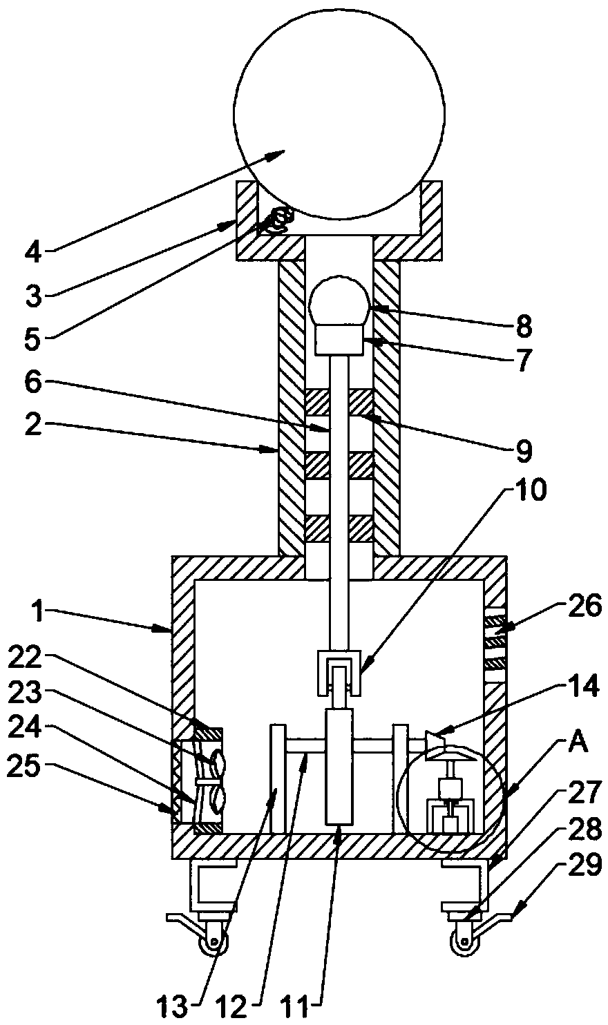
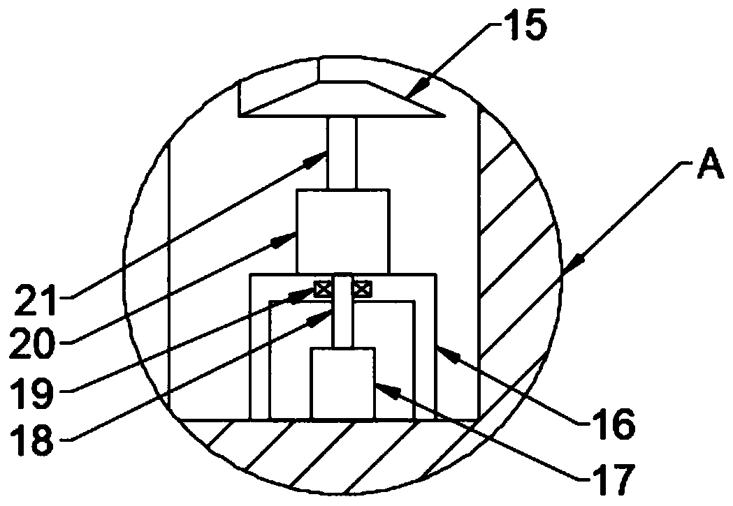
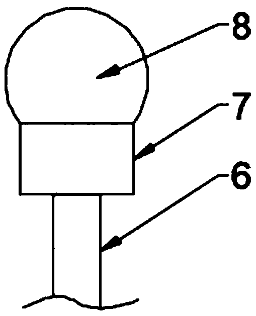
[0025] Embodiment 1, start the motor 17, the motor 17 drives the driving bevel gear 15 to rotate through the reducer 20, the driving bevel gear 15 drives the driven bevel gear 14 to rotate at a high speed, and then drives the cam 11 on the first rotating shaft 12 to rotate, the cam 11 The cam 11 The top wheel 10 is lifted from the starting end, thereby jacking up the hammer rod 6, so that the hammer 7 rises rapidly, hits the volleyball 4, and the volleyball 4 rises rapidly. After the volleyball 4 is hit by the hammer 7, there are two flight stages, one flight The stage is the rising stage of volleyball 4. During the period until volleyball 4 reaches the highest point, the practitioner can practice smashing with the machine. This situation is very close to the situation on the field; String 5 gives volleyball 4 a force effect, makes volleyball descend stage to deviate from normal, is close to the smash ball given by hostility, can selectively practice reaction speed.

Embodiment 2

[0026] Embodiment 2, this embodiment is a further elaboration of Embodiment 1, the bottom end of the left side of the seat box 1 is connected to the intake pipe 22 through, and the inner cavity of the intake pipe 22 is provided with a protective net 25 and an air suction fan 23. The protective net 25 is arranged on the left side of the suction fan 23, and the suction fan 23 is fixedly connected to the inner pipe wall of the air intake pipe 22 through the connecting rod 24, and the top of the right end of the seat box 1 penetrates through Connect the exhaust window 26, the exhaust window 26 is a louver, through the setting of the intake pipe 22 and the exhaust window 26, the ventilation effect of the seat box 1 is greatly improved, which is beneficial to the discharge of heat in the seat box 1, ensuring that the equipment It runs smoothly.


PUM


Abstract

The invention discloses volleyball smash training equipment which comprises a seat box, a guide pipe and a seat cylinder, wherein the guide pipe is connected with the middle of the top end face of theseat box in a communicating manner; the seat cylinder is connected with the top end of the guide pipe in a communicating manner; a volleyball is arranged in an opening in the top end of the seat cylinder; the bottom wall of the cavity of the seat cylinder is connected with the volleyball through a cotton rope; a hammer rod is arranged in the guide pipe; a jacking wheel is fixedly connected with the bottom end of the hammer rod; a driving hammer matched with the volleyball is arranged at the top end of the hammer rod; a protective mat is arranged at the top end of the driving hammer in a sleeving manner; a plurality of sliding plates matched with the guide pipe are uniformly arranged on the excircle surface of the hammer rod in a sleeving manner; a bracket and two support plates are arranged on the base of the cavity of the seat box; and a cam matched with the jacking wheel is arranged between the two support plates. According to the volleyball smash training equipment, the cam is driven by a motor to rotate to further jack up the jacking wheel, the jacking wheel pushes the hammer rod to ascend, and the volleyball is beaten through the driving hammer to be thrown upwards, so that apracticer practices smash; the driving hammer beats the volleyball to ascend to completely fit volleyball throwing cooperation on a playing area, so that simulation of the playing area environment isfacilitated and the practice quality is improved.

Description

technical field [0001] The invention relates to the field of volleyball training equipment, in particular to a volleyball spiking training equipment. Background technique [0002] Volleyball is one of the ball games. The court is rectangular with a high net in the middle. Both sides (six players on each side) occupy one side of the court. Players hit the ball back and forth from the net with their hands. The ball used in volleyball is made of sheepskin or artificial leather, and the rubber is used as the bladder. The size is similar to that of a football. [0003] The sport originated in the United States. In 1895, a sportsman named William G. Morgan invented it in Holyoke, Massachusetts (formerly known as Massachusetts). [1] In the early days, volleyball was called Mintonette (meaning small net). In 1896, according to the characteristics of the game, Professor Halstead proposed to change it to Volleyball (air shot), which is the modern international name Volleyball (volle...

Claims


Application Information

Patent Timeline
Patent Type & Authority Applications(China)
IPC IPC(8): A63B69/00
CPCA63B69/0095
Inventor 陆艳
Owner NANJING XIAOZHUANG UNIV
Why Eureka
Try Eureka