Rotary spraying device

A technology of rotating spraying and spraying pipes, applied in the directions of spraying devices, liquid spraying devices, etc., can solve the problem of low reliability of use, one end is connected to the paint tank, the other end of the spraying pipe is provided with a spray gun, and the spray gun is provided with an on-off valve , the support plate is installed under the workbench, the motor is installed at the top of the support plate, the reducer is installed at the top output end of the motor, and the top output end of the reducer is provided with a rotating shaft, the top of the rotating shaft passes through the bottom end of the workbench Through the worktable and connected with the bottom middle of the turntable, the top of the turntable is set, slow, etc., to improve the reliability of use, save manpower, and ensure uniformity.

Inactive Publication Date: 2018-11-20
JIANGSU ZIQIANG COATING MACHINERY
View PDF0 Cites 9 Cited by
  • Summary
  • Abstract
  • Description
  • Claims
  • Application Information

AI Technical Summary

Problems solved by technology

[0002] As we all know, the workpiece often needs to be sprayed on the surface during processing. The rotary spraying device is an auxiliary device for spraying the workpiece, and it has been widely used in the field of workpiece processing; the existing rotary spraying device includes work platform, turntable, motor, reducer, support plate, paint box and spraying pipe, the paint box is provided with an air compressor, one end of the spraying pipe is connected with the paint box, the other end of the spraying pipe is provided with a spray gun, and the spray gun is provided with a On-off valve, the support plate is installed under the workbench, the motor is installed on the top of the support plate, the reducer is installed at the top output end of the motor, and a rotating shaft is installed at the top output end of the reducer. The end passes through the worktable and connects with the bottom middle of the turntable. There are multiple sets of fixed plates on the top of the turntable. The sets of fixed plates are installed on the outs

Method used


Image

  • Rotary spraying device
  • Rotary spraying device
  • Rotary spraying device

Examples


Embodiment Construction

[0019] The specific implementation manners of the present invention will be further described in detail below in conjunction with the accompanying drawings and embodiments. The following examples are used to illustrate the present invention, but are not intended to limit the scope of the present invention.

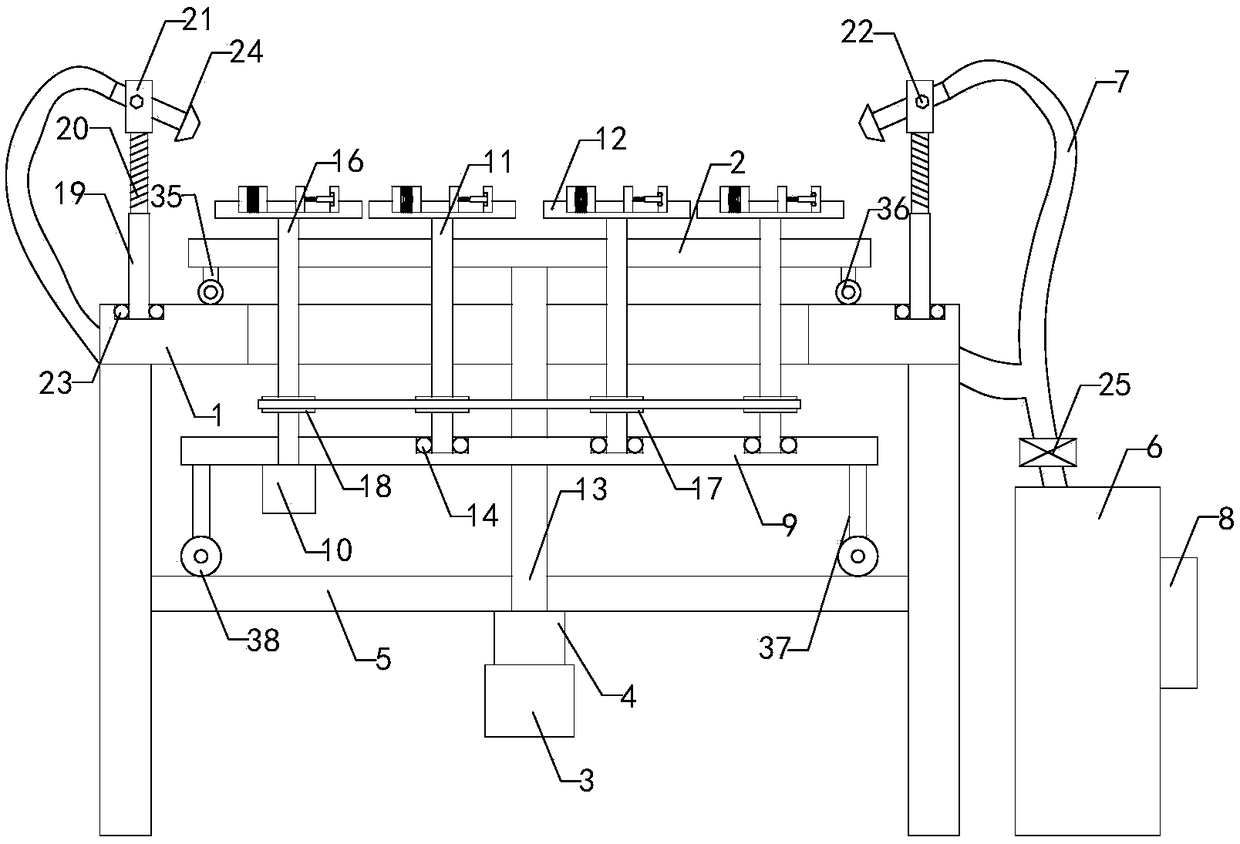
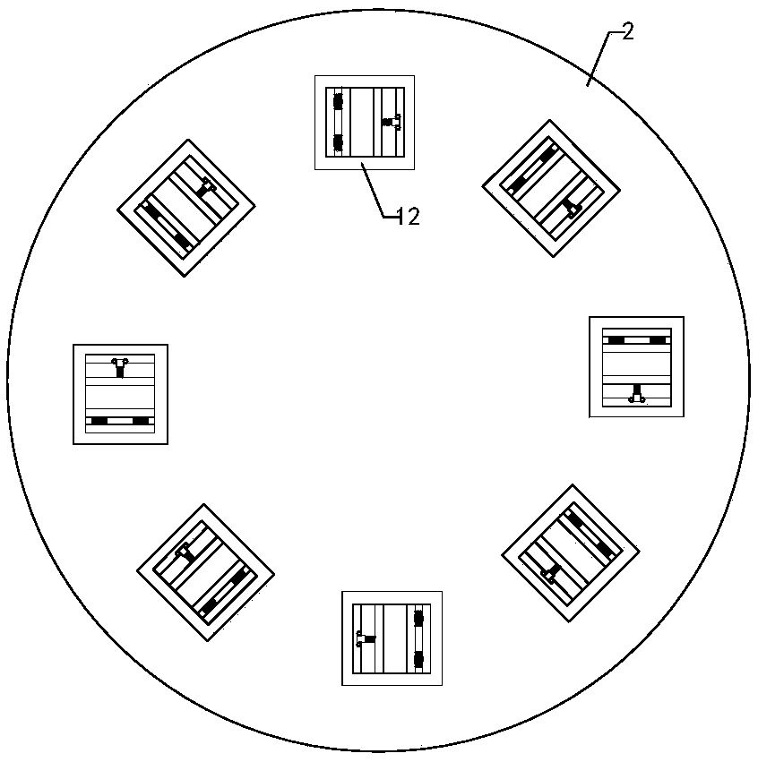
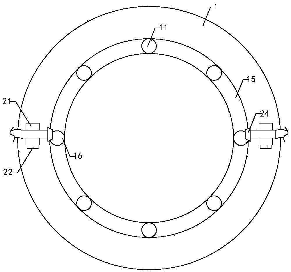
[0020] Such as Figure 1 to Figure 5As shown, a kind of rotary spraying device of the present invention comprises workbench 1, turntable 2, first motor 3, speed reducer 4, support plate 5, paint box 6 and spraying pipe 7, is provided with air compressor 8 on the paint box , one end of the spraying pipe communicates with the paint box, and the support plate is installed under the workbench; it also includes a mounting plate 9, a second motor 10, seven sets of first rotating shafts 11 and eight sets of fixed disks 12, and the middle part of the mounting plate is provided with a fixed The through hole, the motor and the reducer are all installed at the bottom of the support ...


PUM


Abstract

The invention relates to the technical field of spraying auxiliary devices, in particular to a rotary spraying device; and the rotary spraying device can comprehensively spray workpieces without fixing the workpieces again to improve the use reliability, needs no manual spraying to save the manpower, and can guarantee the workpiece spraying uniformity to improve the practicability. The rotary spraying device comprises a worktable, a turntable, a first motor, a speed reducer, a support plate, a paint box, a spraying pipe, an air compressor, a mounting plate, a second motor, seven sets of firstrotating shafts, eight sets of fixed discs, a transmission shaft and seven sets of first ball bearings; annular through holes, communicating up and down, are formed in the worktable; and eight sets ofthrough holes, communicating up and down, are formed in the turntable by equal angles. The rotary spraying device further comprises a second rotating shaft, seven sets of driven belt wheels, a driving belt wheel, a fixing device, a left thread pipe, a left thread rod, a right thread pipe, a right thread rod, a left adjusting block, a right adjusting block, two sets of adjusting bolts, a left ballbearing, a right ball bearing, a spraying gun and a switch valve.

Description

technical field [0001] The invention relates to the technical field of spraying attachments, in particular to a rotary spraying device. Background technique [0002] As we all know, the workpiece often needs to be sprayed on the surface during processing. The rotary spraying device is an auxiliary device for spraying the workpiece, and it has been widely used in the field of workpiece processing; the existing rotary spraying device includes work platform, turntable, motor, reducer, support plate, paint box and spraying pipe, the paint box is provided with an air compressor, one end of the spraying pipe is connected with the paint box, the other end of the spraying pipe is provided with a spray gun, and the spray gun is provided with a On-off valve, the support plate is installed under the workbench, the motor is installed on the top of the support plate, the reducer is installed at the top output end of the motor, and a rotating shaft is installed at the top output end of th...

Claims


Application Information

Patent Timeline
IPC IPC(8): B05B9/04B05B13/02
CPCB05B9/0403B05B13/0228
Inventor 吕海波宋友高
Owner JIANGSU ZIQIANG COATING MACHINERY
Why Eureka
Try Eureka