Cutting device for filter pins

A shearing device and filter technology, applied in the field of filter production, can solve the problems of increasing labor costs and reducing work efficiency, and achieve the effects of reducing labor costs, improving work efficiency, and reducing pressure

Inactive Publication Date: 2018-11-20
LEIYANG YAXIANG ELECTRONICS TECH
View PDF0 Cites 1 Cited by
  • Summary
  • Abstract
  • Description
  • Claims
  • Application Information

AI Technical Summary

Problems solved by technology

[0003] The purpose of the present invention is to provide a cutting device for filter pins, which has the advantages of high efficiency and solves the problem that the existing cutting work is generally cut manually by workers, which not only reduces the work efficiency, but also increased labor costs

Method used


Image

  • Cutting device for filter pins
  • Cutting device for filter pins
  • Cutting device for filter pins

Examples


Embodiment Construction

[0015] The following will clearly and completely describe the technical solutions in the embodiments of the present invention with reference to the accompanying drawings in the embodiments of the present invention. Obviously, the described embodiments are only some, not all, embodiments of the present invention. Based on the embodiments of the present invention, all other embodiments obtained by persons of ordinary skill in the art without making creative efforts belong to the protection scope of the present invention.

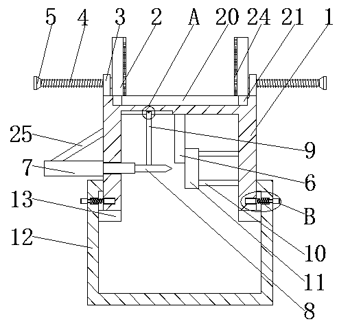
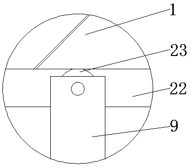
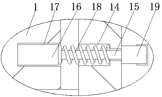
[0016] see Figure 1-3 , a shearing device for filter pins, comprising a working box 1, splints 2 are slidably connected to both sides of the top of the working box 1, and a chute 20 is provided at the front end and the rear end of the top of the working box 1, and the chute 20 The inner chamber of the inner cavity is slidingly connected with a slider 21, and the top of the slider 21 is fixedly connected with the splint 2. By setting the chute 20 and the slide...


PUM


Abstract

The invention discloses a cutting device for filter pins. The cutting device comprises a working box. Clamping plates are slidably connected to the two sides of the top of the working box. Fixing blocks are fixedly connected to the two sides of the top of the working box. Inner cavities of the fixing blocks are in threaded connection with threaded rods. One ends of the threaded rods are fixedly connected with the clamping plates through bearings, and hand wheels are fixedly connected with the ends, away from the clamping plates, of the threaded rods. The top of an inner cavity of the working box is fixedly connected with pin protection tubes which are arranged at intervals. An electric telescopic rod is fixedly connected with the bottom of the left side of the working box. Through coordinate cooperation of the working box, the clamping plates, the fixing blocks, the threaded rods, the hand wheels, the pin protection tubes, the electric telescopic rod, a cutter, a limiting rod, a connecting rod, a cutting board and a material receiving box, the filter pins of different specifications can be mechanically cut, the work efficiency is greatly improved, and the labor cost is reduced.

Description

technical field [0001] The invention relates to the technical field of filter production, in particular to a cutting device for filter pins. Background technique [0002] The filter is a filter circuit composed of capacitors, inductors and resistors. The filter can effectively filter out the frequency points of a specific frequency in the power line or frequencies other than this frequency point, obtain a power signal of a specific frequency, or eliminate a specific frequency. After the frequency of the power signal, the filter needs to cut the pins during production, but the existing cutting work is generally done manually by workers, which not only reduces the work efficiency, But also increased labor costs. Contents of the invention [0003] The purpose of the present invention is to provide a cutting device for filter pins, which has the advantages of high efficiency and solves the problem that the existing cutting work is generally cut manually by workers, which not ...

Claims


Application Information

Patent Timeline
Patent Type & Authority Applications(China)
IPC IPC(8): B21F11/00
CPCB21F11/00
Inventor 陈小勇龚亮朱千林
Owner LEIYANG YAXIANG ELECTRONICS TECH
Why Eureka
Try Eureka