Efficient metal raw material processing pouring device
A metal raw material and high-efficiency technology, applied in metal processing equipment, equipment for feeding molten metal into casting molds, manufacturing tools, etc., can solve problems such as increasing casting costs, and achieve stable casting, reasonable design, and good safety.
- Summary
- Abstract
- Description
- Claims
- Application Information
AI Technical Summary
Problems solved by technology
Method used
Image

Examples
Embodiment Construction
[0015] In order to make the technical means, creative features, goals and effects achieved by the present invention easy to understand, the present invention will be further described below in conjunction with specific embodiments.
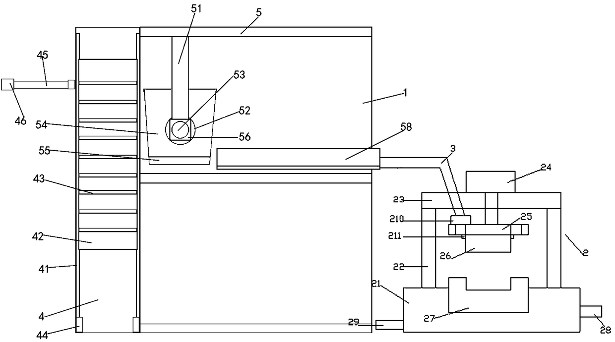
[0016] Such as figure 1 As shown, a high-efficiency metal raw material processing pouring device of the present invention includes a frame 1, a push mechanism is provided on one side of the frame 1, a melting mechanism is provided on one side of the push mechanism, and a pouring mechanism 2 is connected to the melting mechanism;
[0017] The push mechanism includes a cabinet 4, the cabinet 4 is located on one side of the frame 1, and the inside two sides of the cabinet 4 are vertically provided with slide rails 41, and a storage box 42 is vertically connected between the slide rails 41, and a storage box 42 is horizontally arranged in the storage box 42. Several layers of shelves 43 are used to store metal raw materials to be processed on the shel...
PUM
 Abstract
Description
Claims
Application Information