
Multipurpose fixing device for automobile axle type component machining

A part processing and fixing device technology, applied in the field of automobile parts processing, can solve the problems of low versatility and single use of the fixing device, and achieve the effects of good fixing effect, lower production cost and high matching.

Inactive Publication Date: 2018-11-20
ANQING JIAN AUTO PART FORGING & ROLLING
View PDF13 Cites 8 Cited by
  • Summary
  • Abstract
  • Description
  • Claims
  • Application Information

AI Technical Summary

Problems solved by technology

[0003] The purpose of the present invention is to solve the problem of low versatility and single purpose of the fixing device in the prior art, and propose a multi-purpose fixing device for the processing of automobile shaft parts

Method used


Image

  • Multipurpose fixing device for automobile axle type component machining
  • Multipurpose fixing device for automobile axle type component machining
  • Multipurpose fixing device for automobile axle type component machining

Examples


Embodiment 1

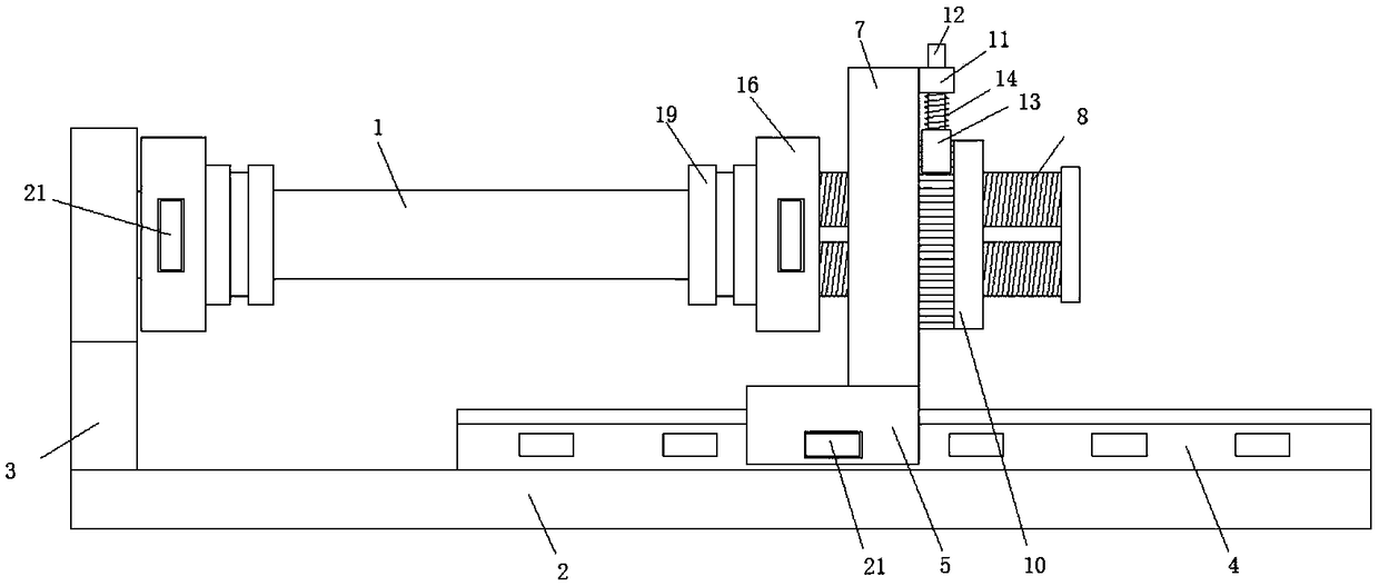
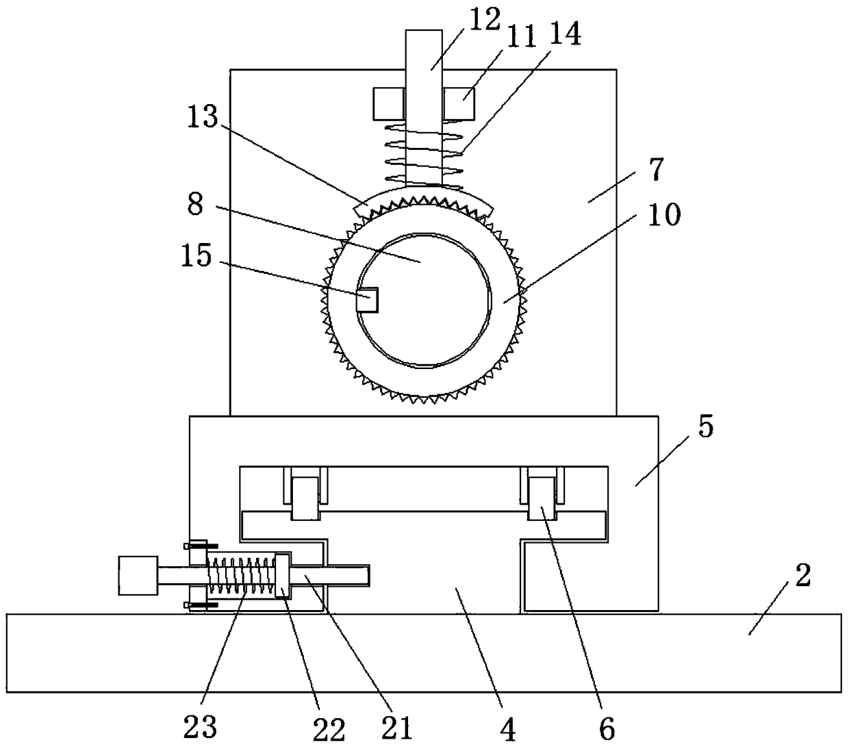
[0025] refer to Figure 1-4 , a multi-purpose fixing device for the processing of automobile shaft parts, comprising a horizontal shaft 1, a bottom plate 2 is arranged vertically below the horizontal shaft 1, a side plate 3 and a T-shaped column 4 are fixedly welded on the top of the bottom plate 2, and the T-shaped column The top sliding sleeve of 4 is provided with a sliding sleeve 5, the bottom side of the sliding sleeve 5 is provided with a T-shaped groove, the top side of the T-shaped column 4 is provided with a track groove, and the top side inner wall of the T-shaped groove is fixedly provided with a track wheel 6 And slidingly connected in the track groove, the top side of the sliding sleeve 5 is fixedly welded with a vertical plate 7, and the body of the vertical plate 7 is provided with a horizontal through hole, and the horizontal through hole is provided with a threaded horizontal column 8, and a threaded horizontal column 8 Limiting chute is set on one side of the...

Embodiment 2

[0028] Such as Figure 1-4 As shown, this embodiment is basically the same as Embodiment 1. Preferably, the adjustment mechanism includes a horizontal plate 11, a control rod 12, an arc gear plate 13 and a return spring one 14, and the horizontal plate 11 is fixedly welded on one side of the vertical plate 7 And offer vertical through hole, the bar body of control rod 12 passes through in vertical through hole, arc gear plate 13 is fixedly welded on the bottom of control rod 12, the outer wall of threaded ring 10 and the bottom of arc gear plate 13 The sides are provided with tooth grooves and meshed with each other.

[0029] In this embodiment, the setting of the adjustment mechanism enables the distance between the splints 19 to be adjusted in a small range, so that the precision of the device is higher and the fixing effect is better.

Embodiment 3

[0031] Such as Figure 1-4 As shown, this embodiment is basically the same as Embodiment 2. Preferably, the return spring one 14 is arranged between the horizontal plate 11 and the arc-shaped gear plate 13 and sleeved on the outside of the rod body of the control rod 12 .


PUM


Abstract

The invention discloses a multipurpose fixing device for automobile axle type component machining. The multipurpose fixing device comprises a transverse shaft. A bottom plate is vertically arranged below the transverse shaft. A side plate and a T-shaped stand column are fixedly welded to the top of the bottom plate. The top of the T-shaped stand column is sleeved with a sliding sleeve in a slidingmanner. A T-shaped groove is formed in the bottom side of the sliding sleeve. A track groove is formed in the top side of the T-shaped stand column. Track wheels are fixedly arranged on the inner wall of the top side of the T-shaped groove and are in sliding connection into the track groove. A vertical plate is fixedly welded to the top side of the sliding sleeve, a horizontal through hole is formed in a plate body of the vertical plate and internally provided with a threaded transverse column, a limiting sliding groove is formed in one side of a column body of the threaded transverse column,a limiting transverse rod is fixedly welded to the inner wall of one side of the horizontal through hole, the limiting transverse rod is horizontally arranged and is in sliding connection into the limiting sliding groove. According to the multipurpose fixing device for automobile axle type component machining, the automobile axle type component fixing effect is better, precision is higher, the application range is wider, operation is convenient, and the usage requirements of people in production and life are met.

Description

technical field [0001] The invention relates to the technical field of automobile parts processing, in particular to a multipurpose fixing device for processing automobile shaft parts. Background technique [0002] Now in the process of automobile production, it is often necessary to perform a series of processing such as grinding, grooving and drilling on shaft parts, but these shaft parts are inconvenient to fix, and the fixing devices are specific, and they are not mutually related. General use, leading to an increase in production costs. At the same time, in the process of processing, sometimes it is necessary to rotate the shaft parts at high speed, and the existing fixing device cannot make the shaft parts differently fixed and rotated. Moreover, the two ends of some long shaft parts are sealed irregularly, which makes people often use the shaft to fix the shaft instead of the two ends of the shaft, resulting in the processing of the shaft part to be carried out many t...

Claims


Application Information

Patent Timeline
Patent Type & Authority Applications(China)
IPC IPC(8): B23Q3/06B24B41/06
CPCB23Q3/06B24B41/061
Inventor 査凌宇
Owner ANQING JIAN AUTO PART FORGING & ROLLING
Learn More