
I-shaped wooden beam quick positioning and mounting device

A technology for positioning installation and wooden beams, which is applied in the field preparation of formwork/formwork/work frame, building components, construction, etc., can solve the problems of difficulty in controlling spacing and low efficiency, and achieve reduced construction risk and simple structure , the effect of improving efficiency and accuracy

Pending Publication Date: 2018-11-20
CHINA CONSTR SIXTH ENG DIV CORP
View PDF6 Cites 2 Cited by
  • Summary
  • Abstract
  • Description
  • Claims
  • Application Information

AI Technical Summary

Problems solved by technology

[0003] The present invention aims to solve the technical problems of low efficiency and difficult distance control of the traditional I-shaped wooden beam installation method, and provides a fast positioning and installation device for I-shaped wooden beams, so that operators can accurately position the I-shaped wooden beams on the ground. Installation, easy to position and install I-shaped wooden beams with different spacing, greatly improve the efficiency and accuracy of wooden beam installation work, and reduce the construction risk

Method used


Image

  • I-shaped wooden beam quick positioning and mounting device
  • I-shaped wooden beam quick positioning and mounting device
  • I-shaped wooden beam quick positioning and mounting device

Examples


Embodiment Construction

[0023] In order to further understand the content, characteristics and effects of the present invention, the following examples are given, and detailed descriptions are as follows in conjunction with the accompanying drawings:

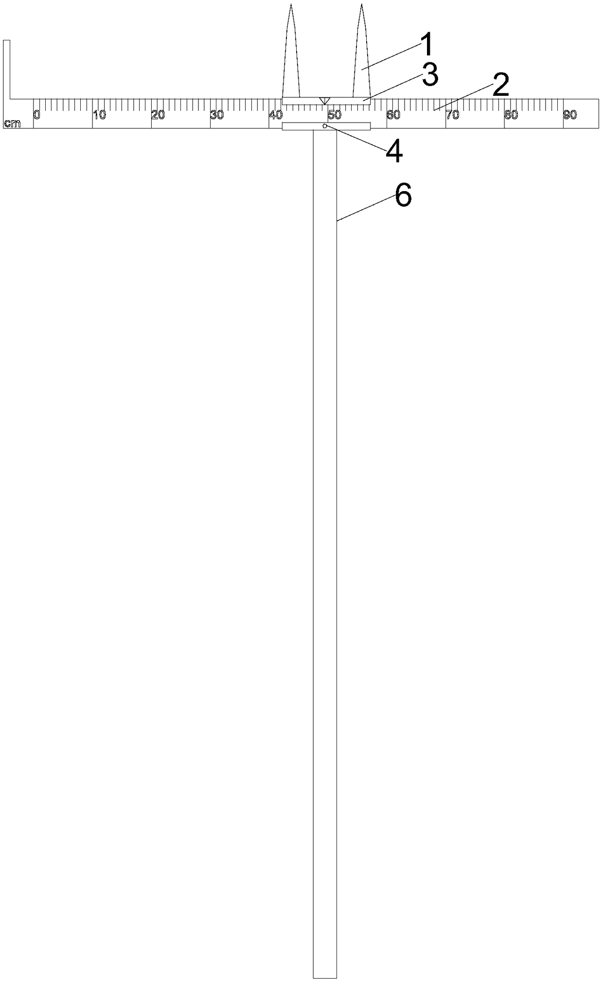
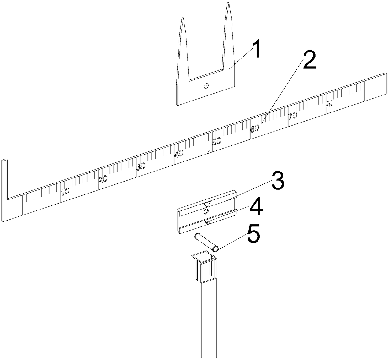
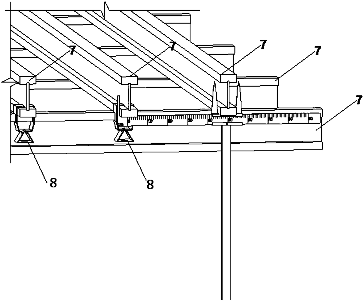
[0024] Such as Figure 1 to Figure 2 As shown, this embodiment provides a fast positioning and installation device for an I-shaped wooden beam, which mainly includes two prong heads 1 , a steel ruler 2 , a C-shaped slot 3 , fastening bolts 4 , rivets 5 , and fork rods 6 . The two prongs 1 are installed in the middle of the top of the fork rod 6, and the C-shaped card slot 3 is installed in the front part of the top of the fork rod 6. The two prongs 1 and the C-shaped card slot 3 are fixed on the fork rod 6 by rivets 5; the steel ruler 2 It is installed in the C-shaped card slot 3 and fixed with the C-shaped card slot 3 by fastening bolts 4 . One end of the steel ruler 2 is provided with a limit clip to locate the steel ruler 2 on the adjacent I-shaped...


PUM


Abstract

The invention belongs to the technical field of construction of slab forms in building engineering, and discloses an I-shaped wooden beam quick positioning and mounting device. The I-shaped wooden beam quick positioning and mounting device comprises a fork lever, wherein a dual-sharp fork head and a C-shaped clamping slot are fixedly mounted / formed at / in the top end of the fork lever through a rivet; a steel rule is mounted in the C-shaped clamping slot and is fixed to the C-shaped clamping slot through a fastening bolt; the dual-sharp fork head comprises two sharp fork teeth which are vertically arranged upwards and a connecting part under the sharp fork teeth; a graduation is marked on the steel rule, and a limiting clamping strip which extends upwards and is perpendicular to a steel rule main body part is arranged at one end of the starting graduation of the graduation; a groove is formed in the surface of the C-shaped clamping slot, and is used for enabling the C-shaped clamping slot to be clamped and fixed to the steel rule; the dual-sharp fork head is mutually parallel to the steel rule; the upper end of the connecting part of the dual-sharp fork head is level with the upperend of the steel rule. Through the adoption of the I-shaped wooden beam quick positioning and mounting device disclosed by the invention, operators can accurately mount I-shaped wooden beams on the ground, the I-shaped wooden beams of different intervals are convenient to position and mount, the working efficiency and the working accuracy of the mounting of the wooden beams are greatly improved, and the risk of the construction is reduced.

Description

technical field [0001] The invention belongs to the technical field of floor formwork construction in construction engineering, and in particular relates to a quick positioning and installation device for I-shaped wooden beams. Background technique [0002] Various support systems such as steel pipe fasteners or bowl frames are often used in the conventional floor formwork support. The I-shaped wooden beam system with scattered branches and dismantling is similar to the steel pipe fastener type bowl frame system. Composed of rods, U brackets, I-shaped wooden beams, and formwork. The tripod is used to temporarily reinforce the steel support. The system integrity is poor and unstable when the system is not fully completed. The function of the steel support vertical rod is similar to that of the bowl frame. Beams are used as primary and secondary beams of the formwork system. When installing secondary I-shaped wooden beams, the operators often stand on the unreinforced frame b...

Claims


Application Information

Patent Timeline
Patent Type & Authority Applications(China)
IPC IPC(8): E04G11/50E04G21/18
CPCE04G11/50E04G21/1841
Inventor 冯建胜吕若辰李胜滔魏宸赵兴亮许仕达
Owner CHINA CONSTR SIXTH ENG DIV CORP
Learn More