A disc entrainment self-priming valve

A self-priming valve, disc technology, applied in the direction of lift valve, valve details, valve device, etc., can solve the problem of shortening the self-priming time, prolong the self-priming start time, reduce the self-priming efficiency, and occupy a small space and volume. Effect

Active Publication Date: 2020-05-05
JIANGSU UNIV
View PDF5 Cites 0 Cited by
  • Summary
  • Abstract
  • Description
  • Claims
  • Application Information

AI Technical Summary

Problems solved by technology

Moreover, the entire valve body is installed above the volute, which can effectively overcome the defects of low entrainment efficiency of the inlet pipeline, so that the disc entrainment self-priming valve can quickly discharge the air in the pump chamber, and significantly shorten the consumption of the self-priming process. time

Method used


Image

  • A disc entrainment self-priming valve
  • A disc entrainment self-priming valve
  • A disc entrainment self-priming valve

Examples


Embodiment Construction

[0033] The present invention will be further described below in conjunction with the accompanying drawings and specific embodiments, but the protection scope of the present invention is not limited thereto.

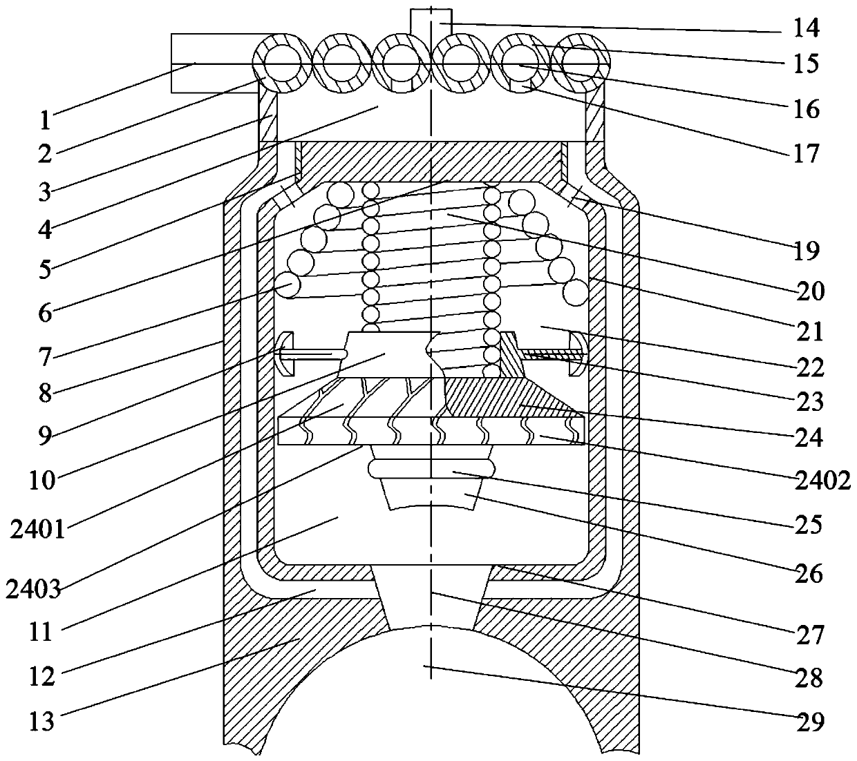
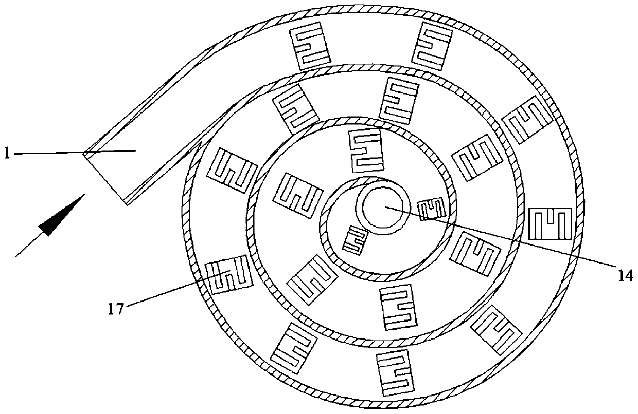
[0034] Such as figure 1As shown, a disc entrainment type self-priming valve according to the present invention comprises a entrainment disc lower cover plate 2, an entrainment disc upper cover plate 15, a first housing 3, a second housing 8, Conical spring 7, connecting spring 20, separating disc 24 and stop plug 26, entrainment disc lower cover plate 2 and entrainment disc upper cover plate 15 fit each other to form a spiral disc entrainment cavity 16, so The disc entrainment chamber 16 is formed by a circular pipeline in a horizontal plane spiraling in a spiral direction, the inlet of the disc entrainment chamber 16 is connected with the air intake pipe 1 in a tangential direction, and the disc entrainment chamber The outlet of 16 is located at the center of disc entra...


PUM


Abstract

The invention provides a disc entrainment type self-suction valve. The disc entrainment type self-suction valve comprises a first shell, a second shell and an entrainment disc, wherein a valve body isprovided with an entrainment outer cavity and an entrainment inner cavity, a connecting spring is installed on the top wall of the second shell, and a separation disc is connected to the bottom end of the connecting spring; the separation disc divides the entrainment inner cavity into an upper entrainment inner cavity and a lower entrainment inner cavity, and the entrainment inner cavity communicates with an inner cavity of a volute through a communication hole; a communication stop plug is mounted on the lower surface of the separation disc, and an upper cover plate of the entrainment disc is fitted to a lower cover plate of the entrainment disc to form a disc entrainment cavity; and an entrainment through hole is formed in the lower cover plate of the entrainment disc to complete the entrainment of air in a pump. The disc entrainment type self-suction valve adopts a disc entrainment type structure to significantly increase the entrainment efficiency of the device while the volume ofthe space is reduced, and realizes opening and closing of the valve body by separating the disc and the connecting spring and adjusting the opening degree according to the self-suction stage, the energy consumption is reduced, and the self-suction efficiency is improved.

Description

technical field [0001] The invention relates to a self-priming valve, in particular to a disc entrainment type self-priming valve. Background technique [0002] Because of its unique self-priming principle, self-priming valves are widely used in emergency water delivery projects such as agricultural machinery, urban drainage, emergency rescue and disaster relief. However, the traditional self-priming valve usually adopts a linear structure. The single-stage linear self-priming structure has a small space volume, but its efficiency is low, which cannot meet the needs of users. Although the efficiency of the multi-stage linear self-priming structure has been significantly improved, it takes up The space is large, and there will be obvious vibration and noise during operation, and it is difficult to transport and operate. At the same time, the traditional self-priming valve is generally installed in the inlet pipeline of the pump, which can easily lead to the early stage of th...

Claims


Application Information

Patent Timeline
Patent Type & Authority Patents(China)
IPC IPC(8): F16K1/32F16K1/38F16K27/02F16K31/12
CPCF16K1/32F16K1/385F16K27/0254F16K31/12
Inventor 常浩施卫东李伟刘建瑞王川周岭
Owner JIANGSU UNIV
Why Eureka
Try Eureka