Eureka AIR delivers breakthrough ideas for toughest innovation challenges, trusted by R&D personnel around the world.

Supersonic flow channel design method and apparatus

A supersonic flow and design method technology, applied in design optimization/simulation, turbine/propulsion device inlet, calculation, etc., can solve the problem that the aerodynamic performance of the inlet is difficult to control the total/internal contraction ratio of the inlet, etc. Achieve the effect of adjustable and controllable geometric parameters and excellent performance

Active Publication Date: 2018-11-20
NAT UNIV OF DEFENSE TECH
View PDF5 Cites 15 Cited by
  • Summary
  • Abstract
  • Description
  • Claims
  • Application Information

AI Technical Summary

Problems solved by technology

[0012] The present invention provides a hypersonic inlet design method and device, which are used to overcome the defects in the prior art that it is difficult to ensure the aerodynamic performance of the inlet, and it is difficult to control the geometric parameters such as the total / internal contraction ratio of the inlet. The aerodynamic performance of the inlet port is optimal and the geometric constraints are met as the goal, the aerodynamic performance of the inlet port is optimized, and the controllability of the geometric parameters of the inlet port is improved

Method used


Image

  • Supersonic flow channel design method and apparatus
  • Supersonic flow channel design method and apparatus
  • Supersonic flow channel design method and apparatus

Examples


Embodiment 1

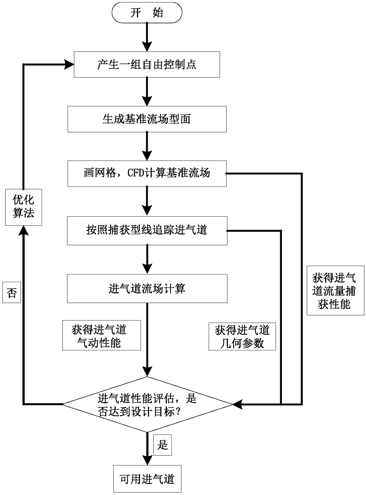
[0037] refer to figure 1 , an embodiment of the present invention provides a hypersonic inlet design method, including the following steps:

[0038] Step S1, according to the preset control parameters, a group of free control points is generated by parameterization method, and the control points are connected by spline curves to generate a reference flow field profile; the preset control parameters include the design condition of the inlet port as Mach number, Pressure, temperature, shrinkage ratio inside the inlet, total shrinkage ratio of the inlet, etc.;

[0039] Step S11, obtaining the wall profile of the reference flow field according to a part of the preset control parameters;

[0040] Step S12, obtaining the coordinates of free control points F1, F2, F3, F4, F5, and F6 according to the preset control parameters described in another part;

[0041] Below in conjunction with concrete design parameter, provide an embodiment:

[0042] According to the overall requirements...

Embodiment 2

[0087] see Figure 7 , an embodiment of the present invention provides a hypersonic inlet design device, including: a reference flow field profile generation module 1, a reference flow field calculation module 2, a streamline tracking module 3, a flow field calculation module 4, and an optimization module 5; in:

[0088] The reference flow field profile generation module 1 is used to generate a group of free control points through a parameterization method according to preset control parameters, and connect the control points with spline curves to generate a reference flow field profile;

[0089] The reference flow field calculation module 2 is used to draw a grid for the reference flow profile obtained by the reference flow profile generation module 1, calculate the reference flow field profile by computational fluid dynamics method to obtain a reference flow field, according to the The flow capture performance parameters of the inlet are obtained from the reference flow fie...


PUM


Abstract

The invention relates to a supersonic flow channel design method and apparatus. The method comprises the following steps: step S1, generating a reference flow field molded surface; step S2, calculating the reference flow field obtained in the step S1; step S3, generating a three-dimensional internal steering air inlet channel by using a streamline tracing method; step S4, calculating the flow field of the three-dimensional internal steering air inlet channel obtained in the step S3; and step S5, repeatedly iterating step S1 to step S5 by using an optimization algorithm to obtain a three-dimensional internal steering air inlet channel meeting traffic capture performance, geometric parameters and aerodynamic performance. Compared with the prior art, the method has the advantages of being able to solve the problems that the traditional air inlet channel design does not directly aim at the aerodynamic performance of the air inlet channel and starts from the reference flow field performance, such that it is difficult to ensure the same performance of the air inlet channel, the experience is too high to ensure the optimal value of the performance of the air inlet channel and that the total shrinkage ratio and the internal shrinkage ratio of the internal steering air inlet channel are uncontrollable.

Description

technical field [0001] The invention belongs to the technical field of hypersonic propulsion, and relates to a design method of a scramjet inlet, in particular to a hypersonic inlet design method and device. Background technique [0002] The scramjet engine is a power component of a hypersonic vehicle (a vehicle with a flight Mach number greater than 4), which is mainly composed of four parts: an inlet, an isolation section, a combustion chamber and an exhaust nozzle. The hypersonic inlet is the air supply part of the scramjet engine, which provides sufficient and high-quality incoming flow for the engine combustion chamber to ensure the normal and efficient operation of the engine. [0003] In the current ground research or flight test of hypersonic vehicles, the air intake part adopts a three-dimensional inner turning air inlet. This type of air inlet has the advantages of small total pressure loss, strong flow capture ability, small external resistance and It is convenie...

Claims


Application Information

Patent Timeline
Patent Type & Authority Applications(China)
IPC IPC(8): G06F17/50F02C7/04
CPCF02C7/04G06F30/17G06F30/20
Inventor 熊冰范晓樯蒙泽威王振国刘卫东梁剑寒王翼
Owner NAT UNIV OF DEFENSE TECH
Why Eureka
Eureka Blog
Learn More