A high-power air-type busway

An air-type, high-power technology, which is applied in the direction of fully enclosed busbar devices, can solve the problems of reduced strength of the busbar, the conductivity of the conductive layer cannot reach the conductivity of the busbar, and affect the conductivity of the busbar, so as to prevent local overheating and improve conductivity. performance, pressure uniform effect

Active Publication Date: 2020-04-07
XIANGRONG ELECTRIC GRP
View PDF7 Cites 0 Cited by
  • Summary
  • Abstract
  • Description
  • Claims
  • Application Information

AI Technical Summary

Problems solved by technology

[0004] The air-type insulated busway is one of the most widely used busways. There is a through hole in the middle of the busbar connection of the dense air-insulated busway. When multiple busways are connected, bolts and busbar partitions are used. For connection, there is an insulating layer in the middle of the partition, which plays the role of insulation. The two busbar connection surfaces of the partition are conductive layers, which are used to conduct the corresponding phase paths. There are mainly the following defects when connecting in this way: One is that the conduction of the interconnected phase circuits is realized through the conductive layers of the partitions on both sides, and the ends of the phase circuits are not connected, and the conductivity of the conductive layer cannot reach the conductivity of the busbar; the other is the busbar There are bolt holes at the connection of the busbar. On the one hand, the bolt hole reduces the strength of the busbar, and on the other hand, it also affects its electrical conductivity to a certain extent. When the current is too large, the heat at the connection will be serious. In summary As mentioned above, the joints of the existing bus ducts have become an important factor restricting the transmission power of the bus ducts, so there is an urgent need for a high-power air-type bus duct joint that does not affect the overall strength of the bus duct and can further improve the electrical conductivity of the bus duct connection

Method used


Image

  • A high-power air-type busway
  • A high-power air-type busway
  • A high-power air-type busway

Examples


Embodiment Construction

[0026] The present invention will be further described below in conjunction with the accompanying drawings. The following examples are only used to illustrate the technical solution of the present invention more clearly, but not to limit the protection scope of the present invention.

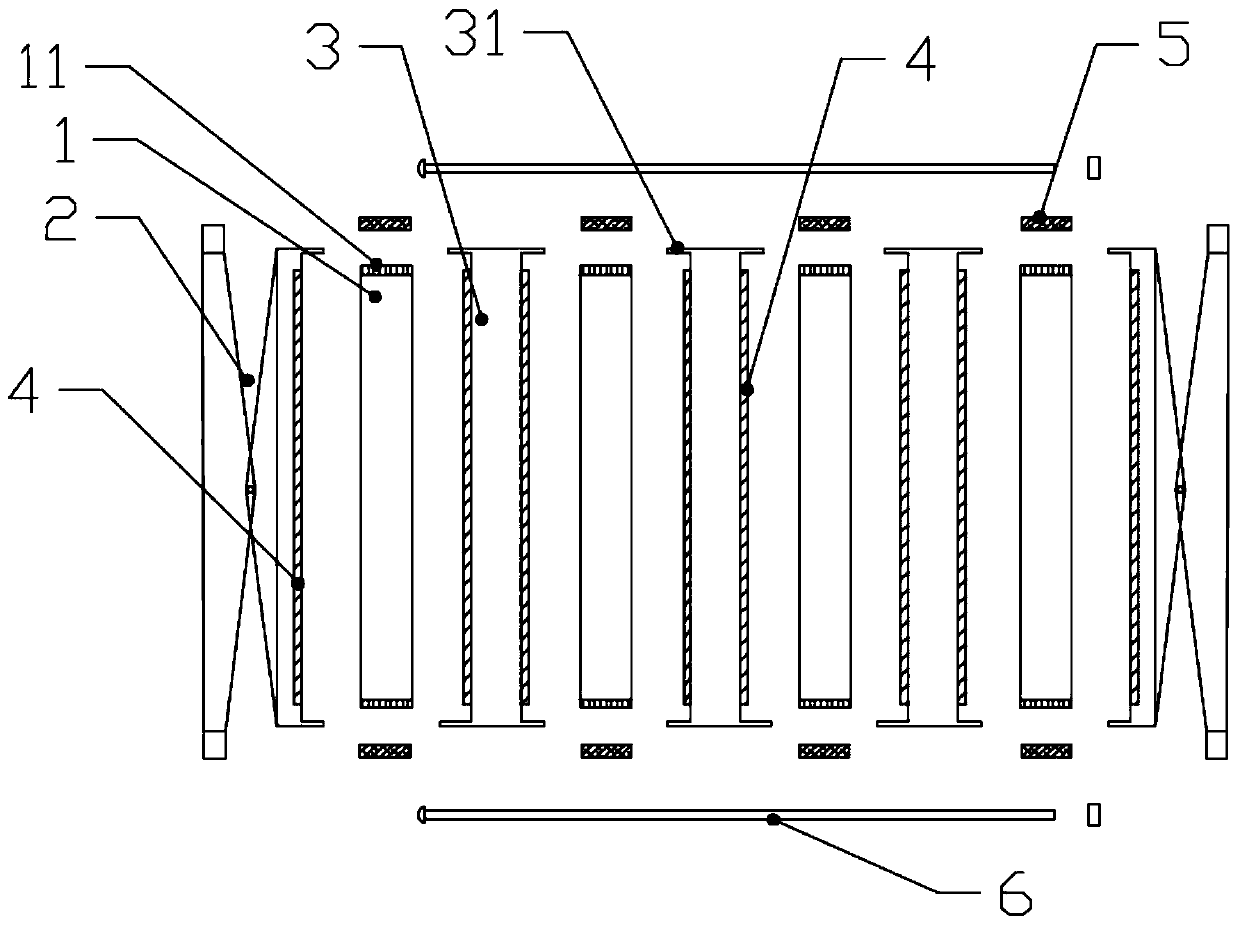
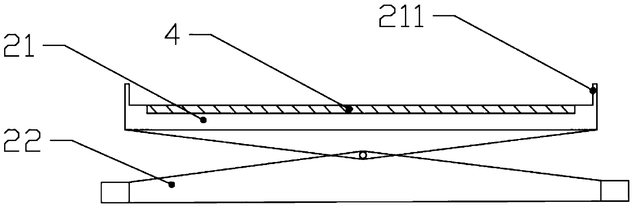
[0027] Such as figure 1 Shown: a high-power air-type busway, including a busbar 1 and a busbar joint for connecting the busbar 1, the busbar joint includes a pressure plate 2, a connecting plate, a wedge plate 7 and a busbar 1 arranged between Insulation partition 3, conductive layer 4 is provided on both sides of pressing plate 2;

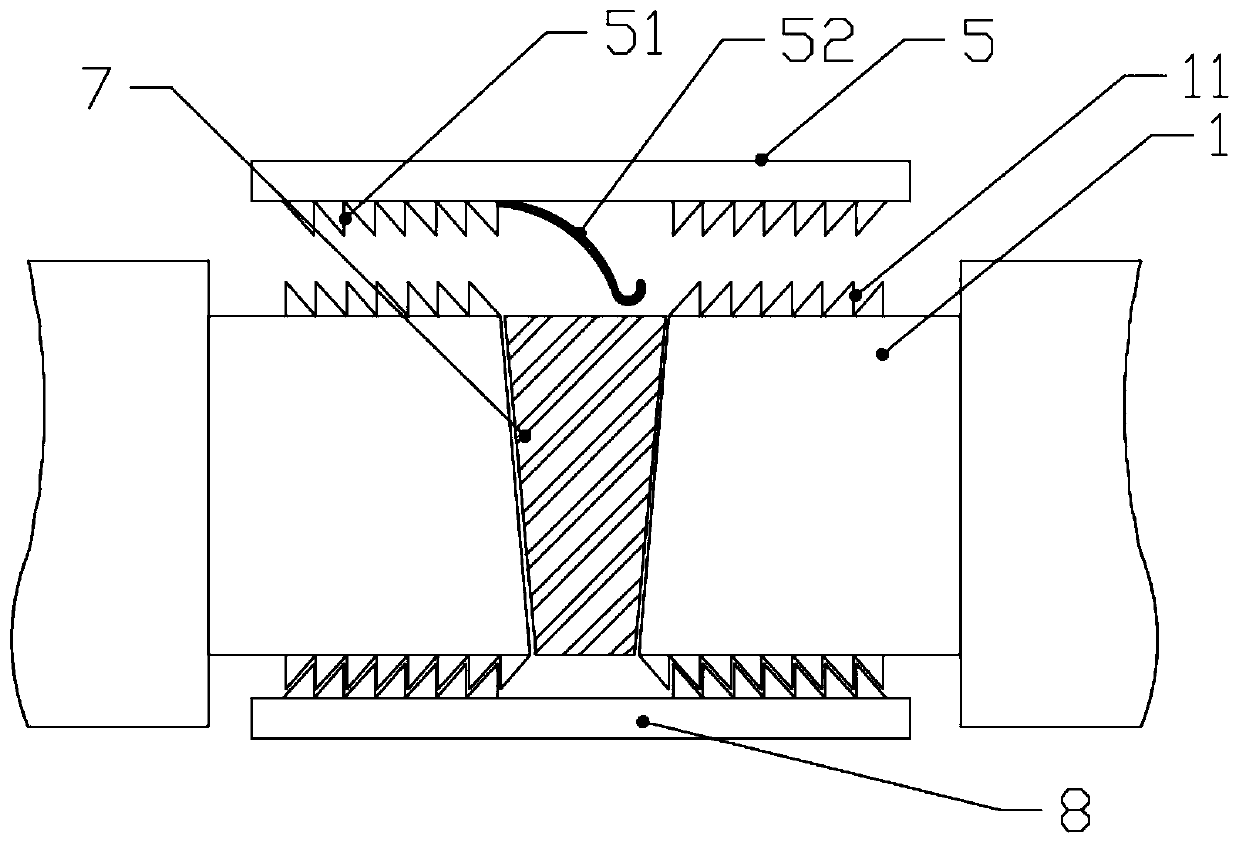
[0028] Such as figure 2 As shown: the side of busbar 1 is provided with busbar side teeth 11, and the connecting plate is provided with ratchet 51, and ratchet 51 is connected to busbar 1 of the same phase (same electrode) through busbar side teeth 11, and busbar 1 The end of the wedge plate is provided with a wedge surface, and the wedge surface of the wedge pl...


PUM


Abstract

The invention discloses a high-power air-type bus slot, comprising a bus bar and a bus bar connector. The bus bar connector comprises a pressing plate, a connecting plate, a wedge-shaped plate and aninsulating separator arranged between the bus bars. Both sides of the pressing plate are provided with conductive layers. The side part of the bus bar is provided with side teeth of the bus bar, the connecting plate is provided with ratchet teeth, the ratchet teeth are connected with the bus bar of the same phase path through the side teeth of the bus bar, the end part of the bus bar is provided with a wedge surface, the wedge surface of the wedge plate is connected with the bus bar of the same phase path, and the wedge angle of the wedge surface of the end part of the bus bar is equal to thewedge angle of the wedge plate; the pressing plate comprises an inner pressing plate and an outer pressing plate which are mutually hinged in the middle, the inner surface of the inner pressing plateis also provided with an electric conductive layer, the two ends of the outer pressing plate are provided with through holes for connecting bolts, and the bolts are connected with a pair of pressing plates for fixing the insulating separator and the bus bar. The invention can also make the end of the bus bar conductive, the pressing plate is enough to ensure the pressure of the inner pressing plate to the bus bar is uniform, which is conducive to improving the conductivity, and the phenomenon of local overheating can be further avoided because the bus bar is not perforated.

Description

technical field [0001] The invention relates to the technical field of power supply, in particular to a high-power air-type bus duct. Background technique [0002] With the emergence of modern engineering facilities and equipment, the power consumption of all walks of life is increasing rapidly, especially the emergence of many high-rise buildings and large workshops. The traditional cables used as power transmission wires can no longer meet the requirements in large current transmission systems. The parallel use of multiple cables brings a lot of inconvenience to the site installation and construction connection. As a new type of distribution wire, the plug-in busway came into being. [0003] Compared with the traditional cables, it fully demonstrates the superiority of the busway when transmitting large currents. At the same time, due to the adoption of new technology and new technology, it greatly reduces the contact between the connection at the two ends of the busway a...

Claims


Application Information

Patent Timeline
Patent Type & Authority Patents(China)
IPC IPC(8): H02G5/06
CPCH02G5/06
Inventor 唐帅万超建
Owner XIANGRONG ELECTRIC GRP
Why Eureka
Try Eureka