Work parameter visualization method for mobile communication network base station

A mobile communication network and base station technology, which is applied in the field of visualization of working parameters of mobile communication network base stations, can solve problems such as poor cell communication, inability to express other information, inability to express downtilt angle and transmit power, etc.

Inactive Publication Date: 2018-11-20
UNIV OF SCI & TECH BEIJING
View PDF2 Cites 4 Cited by
  • Summary
  • Abstract
  • Description
  • Claims
  • Application Information

AI Technical Summary

Problems solved by technology

This method can express the location of the base station and the direction of the antenna through the combination with the map, but it cannot express other information, such as the inclination angle and the transmission power.
When the downtilt angle of some antennas is abnormal, but it is not displayed in the sector mark diagram, it is easy to be ignored, and the abnormality cannot be found in time, resulting in poor communication in the cell

Method used


Image

  • Work parameter visualization method for mobile communication network base station
  • Work parameter visualization method for mobile communication network base station
  • Work parameter visualization method for mobile communication network base station

Examples


no. 1 example

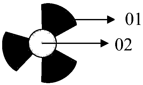
[0043] In the method for visualizing industrial parameters of a mobile communication network base station in this embodiment, the industrial parameters are expressed through element visualization icons. Figure 5Shown is a schematic diagram of the element visualization icon in this embodiment. Such as Figure 5 As shown, the element visualization icon includes: base station element 1, antenna element 2, and hanging height element 3. The methods include:

[0044] A base station is represented by a base station element 1 .

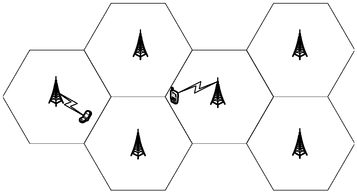
[0045] The base station element 1 is a circle, and its center is located at the location of the base station on the map, so that the geographic location or coordinates of the base station can be known. Base station elements and prior art figure 2 The base station elements are the same in the sector marker diagrams shown.

[0046] The azimuth, downtilt and power of the antenna are represented by antenna element 2 .

[0047] Preferably, the antenna elem...

no. 2 example

[0054] Figure 10 Shown is a schematic diagram of the antenna elements of this embodiment. Place Figure 10 As shown, this embodiment is basically the same as the first embodiment, the difference is that this embodiment performs different levels of filling in the trapezoidal area to represent different powers, and is different from the first embodiment in that it fills in the rectangular area ; The present embodiment utilizes the way that the upper bottom / lower bottom is protruding or concave ( Figure 10 Shown in the way the lower bottom is convex) indicates the downward inclination angle.

[0055] It can be seen from the above that the method for visualizing the industrial parameters of the mobile communication network base station in the embodiment of the present invention can clearly indicate the antenna direction angle, downtilt angle, power, hanging height parameters and the geographical location of the base station, and the downtilt angle and over-tilt angle correspon...


PUM


Abstract

The invention provides a work parameter visualization method for a mobile communication network base station, which represents work parameters by element visualization icons, comprising: representingthe base station by a base station element; representing the direction angle, downward inclination angle and power of the antenna by antenna elements; and representing the height of the antenna by a hanging element. The work parameter visualization method for the mobile communication network base station provided by the invention may clearly represent the direction angle, downward inclination angle, power and hanging parameters of the antenna, and the geographical location of the base station, and is capable of obviously representing abnormal work parameters for a negative downward inclinationangle and an oversize downward inclination angle. At the same time, the invention has certain compatibility with the sector identification method in existing technology.

Description

technical field [0001] The invention belongs to the technical field of network communication, and in particular relates to a visualization method for working parameters (hereinafter referred to as working parameters) of a mobile communication network base station. Background technique [0002] In recent years, the existing mobile communication network is dominated by cellular network, such as figure 1 Shown is a schematic diagram of the cellular network structure in the prior art. By dividing the service area of ​​the network system into small regular hexagonal sub-areas, a base station is set in each small sub-area to achieve communication signal coverage in an area. The base station equipment in each small sub-area is equipped with multiple (directional) antennas to transmit wireless signals in different directions, such as figure 2 Shown is a schematic structural diagram of the antenna shown in the prior art. Normally, each base station includes 3 (there are 2-4 indivi...

Claims


Application Information

Patent Timeline
Patent Type & Authority Applications(China)
IPC IPC(8): H04L12/24H04W24/04
CPCH04L41/22H04W24/04
Inventor 皇甫伟黄鹤林隆克平
Owner UNIV OF SCI & TECH BEIJING
Why Eureka
Try Eureka