Filament cutting head for free trimmer

一种收割头、切割机的技术,应用在切割器、收割机、应用等方向,能够解决切割丝线困难可接近性、切割丝线拆卸困难、不可切割丝线取出等问题

Active Publication Date: 2018-11-23
ANDREAS STIHL AG & CO KG
View PDF8 Cites 2 Cited by
  • Summary
  • Abstract
  • Description
  • Claims
  • Application Information

AI Technical Summary

Problems solved by technology

[0003] It has been found that due to the difficult accessibility of the free ends of the cutting wires, easy removal of the cutting wires is not possible
Difficult removal of the cutting wire especially when using work gloves

Method used


Image

  • Filament cutting head for free trimmer
  • Filament cutting head for free trimmer
  • Filament cutting head for free trimmer

Examples


Embodiment Construction

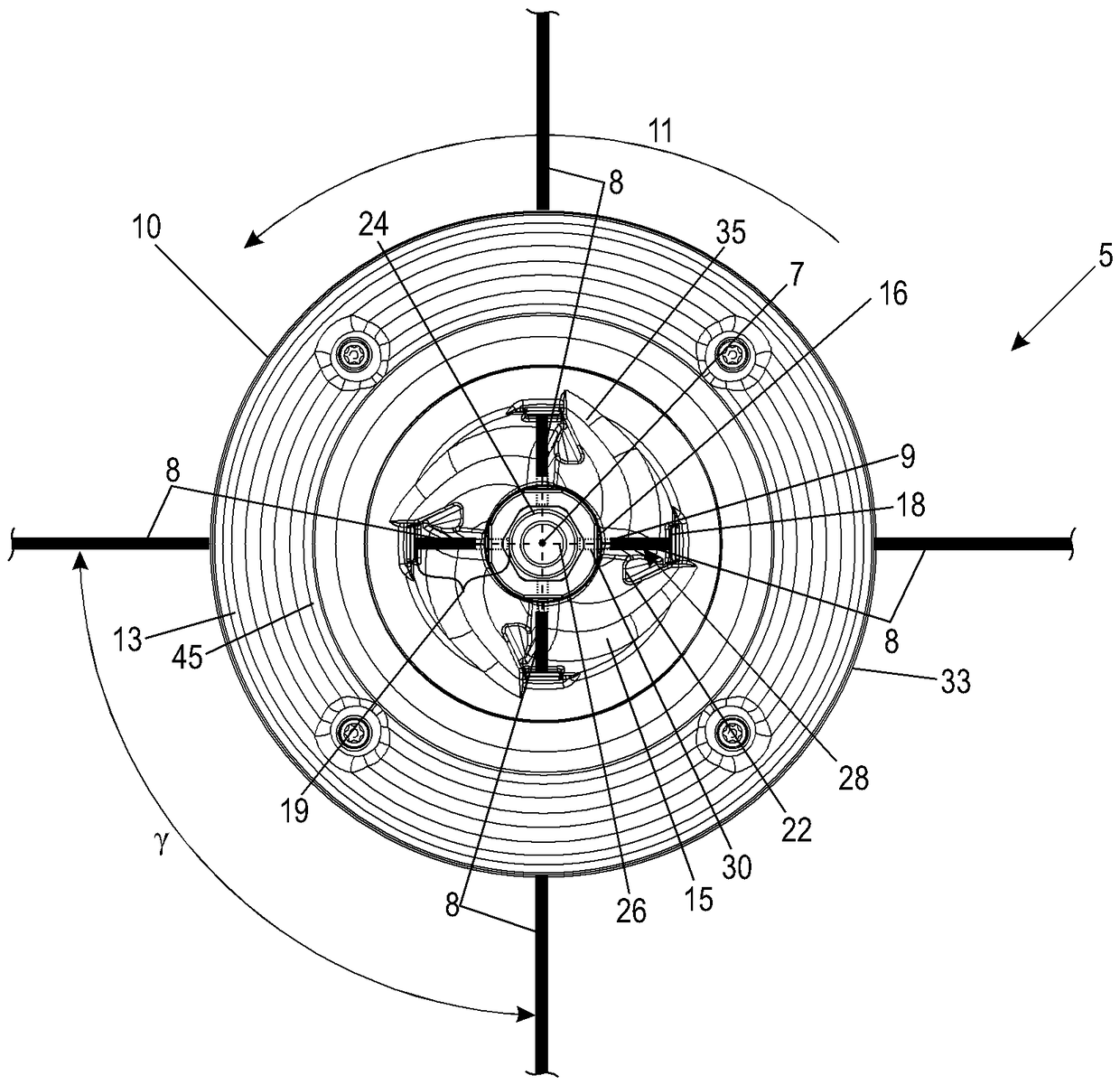
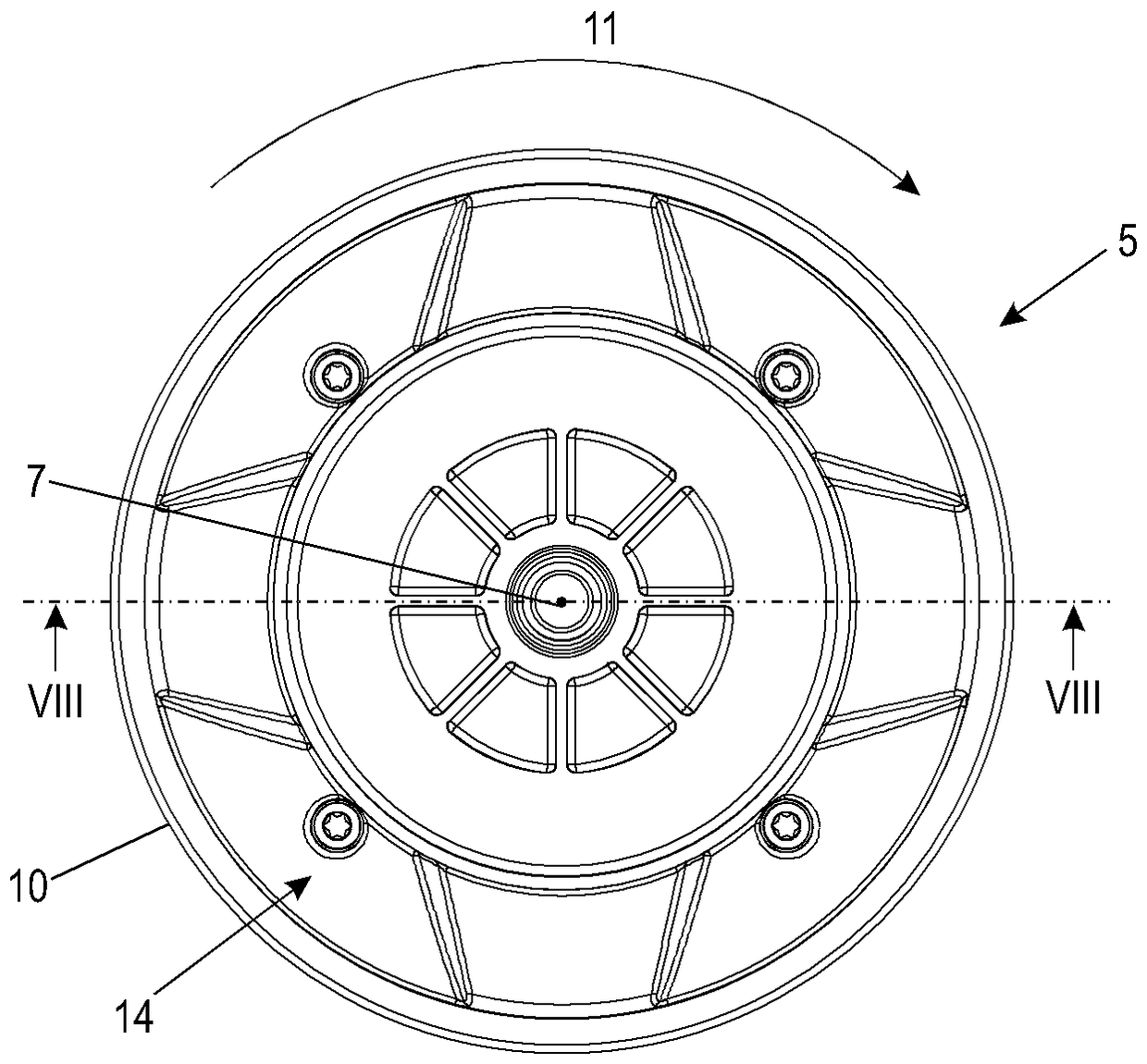
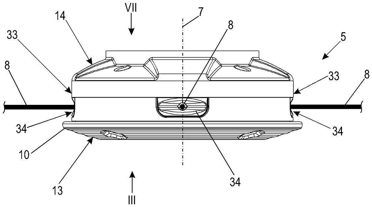
[0030] figure 1 A free cutter 1 is shown schematically, which is held by an operator. Free cutter 1 has a housing 2 in which a drive motor (not shown) is arranged. The free cutter 1 has a shaft 3 which is arranged with one end on the housing 2 and which carries a wire harvesting head 5 with its other end. A drive shaft (not shown) driven by a drive motor arranged in the housing 2 extends through the shaft 3 and drives the silk harvesting head 5 around the axis of rotation 7 . The drive motor can be an internal combustion engine or an electric motor. It can also be provided that the drive motor is arranged at the end of the shaft 3 carrying the wire harvesting head 5 . This is especially advantageous when the drive motor is an electric motor. During operation, the wire harvesting head 5 is covered by a protective cover 6 on the side facing the operator. The wire harvesting head 5 has at least one cutting wire 8 for cutting cuttings such as grass, bushes or the like. The s...


PUM


Abstract

The invention relates to a filament cutting head for a free trimmer, wherein the filament cutting head (5) is rotatingly drivable about a rotational axis (7) in operation. The filament cutting head (5) comprises a basic body (10) on which at least one cutting filament (8) is held. The cutting filament (8) extends from an outside (14) of the basic body (10) through a filament opening (18) into an interior region (15) of the filament cutting head (5) which is open to a surrounding area. A stop (16) for the cutting filament (8) is arranged at the filament cutting head (5), wherein, in a first position (28) of the cutting filament (8), the stop (16) delimits a length (f) of a filament portion (19) of the cutting filament (8), which is insertable into the interior region (15), to an insertion length (b). At least one deflection element (22) is arranged in the interior region (15) of the filament cutting head (5) so that the cutting filament (8) switchable from the first position (28), without the cutting filament (8) being displaced in its longitudinal direction, into a second position (29). The cutting filament (8) abuts against the deflection element (22) in the second position (29) and the stop (16) does not delimit the length (f) of the filament portion (19) which is insertable into the interior region (15).

Description

technical field [0001] The invention relates to a wire harvesting head for a free cutting machine. Background technique [0002] From DE 10 2014 006 057 A1 a wire harvesting head for free-cutting machines is known, which has a base body into which two cutting wires can be pushed from the outside of the wire harvesting head from opposite sides. The free ends of the cutting wires protrude into an interior space that is open towards the bottom side of the wire harvesting head. A shielding element is arranged in the interior, wherein the section of the cutting wire running in the interior is arranged on the rear side of the shielding element with respect to the direction of rotation. To remove the cutting wire, the operator grasps the inner free end of the cutting wire and pulls it inwards. [0003] It has been found that due to the difficult accessibility of the free ends of the cutting wires, easy removal of the cutting wires is not possible. Especially when working gloves ...

Claims


Application Information

Patent Timeline
Patent Type & Authority Applications(China)
IPC IPC(8): A01D34/416
CPCA01D34/416A01D34/4166A01D34/4168A01D34/4165A01D34/4167
Inventor S.朗D.京特
Owner ANDREAS STIHL AG & CO KG
Why Eureka
Try Eureka