
Detection system and method for human-body lower limb hip and knee joint angle

A hip and knee joint and angle detection technology, applied in the field of detection, can solve the problems of reducing measurement effectiveness, increasing data processing time, and inconvenient experiments.

Inactive Publication Date: 2018-11-23
BEIJING UNIV OF TECH
View PDF5 Cites 6 Cited by
  • Summary
  • Abstract
  • Description
  • Claims
  • Application Information

AI Technical Summary

Problems solved by technology

[0003] After reviewing domestic and foreign literature, it is found that the current systems and methods for detecting hip and knee joint angles have the following characteristics: ① The sensors used include micro-accelerometers, gyroscopes, and fiber optic angle sensors, among which the accelerometer or gyroscope is used alone to measure the angle Information will generate certain errors in the process of angle calculation. The method of dealing with this error is generally to find the fluctuation range of the error through a large number of experiments and then make compensation on the corresponding angle, but it will increase the time of data processing and reduce the actual effect of measurement. sex
②The data transmission methods of the detection system mainly include wired and wireless. Wired transmission will cause great inconvenience to the experiment and increase the discomfort of wearing the human body

Method used


Image

  • Detection system and method for human-body lower limb hip and knee joint angle
  • Detection system and method for human-body lower limb hip and knee joint angle
  • Detection system and method for human-body lower limb hip and knee joint angle

Examples


Embodiment Construction

[0020] Hereinafter, the embodiments of the present invention will be described in detail with reference to the drawings.

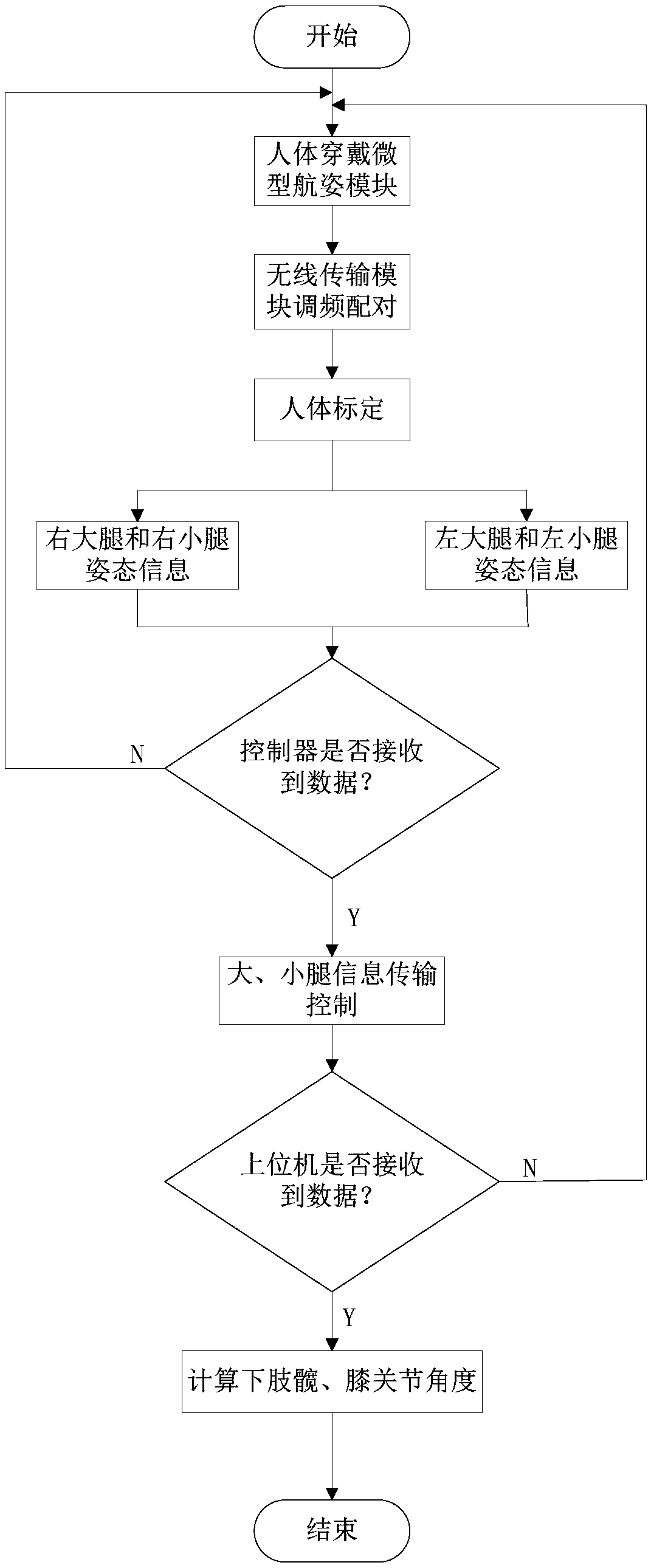
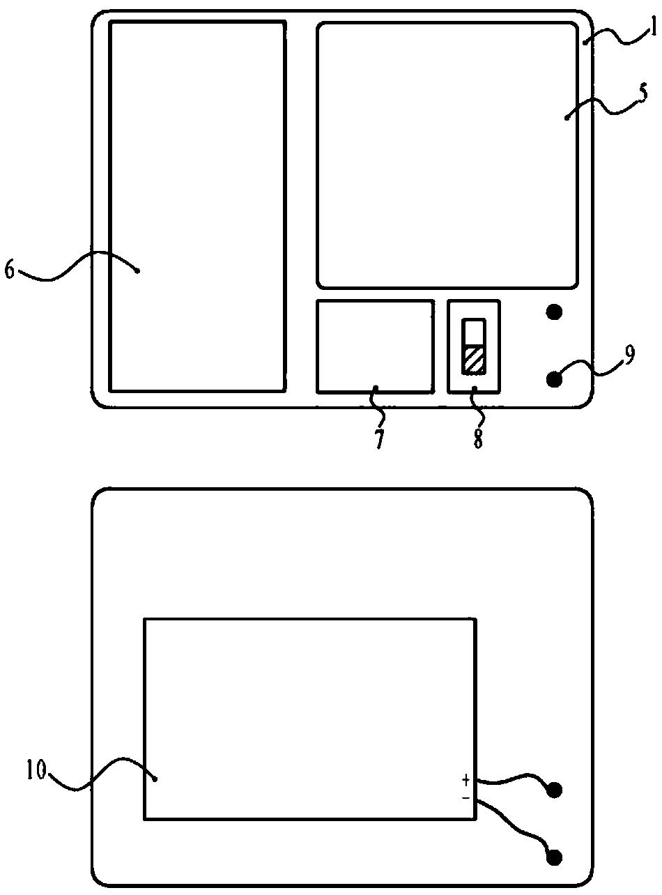
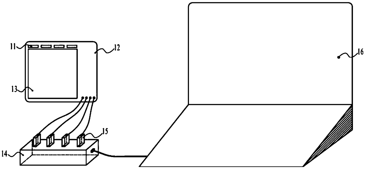
[0021] figure 1 Is the flow diagram of the detection system and method implementation, figure 2 It is the front view and back view of the miniature heading module unit, image 3 Is the connection diagram of the detection system, Figure 4 It is a schematic diagram of human body calibration and wearing miniature heading and attitude module unit, Figure 5 Is a schematic diagram of the human walking process, Image 6 Is a schematic diagram of the connecting rod model of the human body, Figure 7 Is a schematic diagram of the coordinate system, Figure 8 It is the display diagram of the PC application program interface of the detection system.

[0022] This embodiment provides a system and method for detecting the angle of the hip and knee joints of the lower limbs of the human body. figure 1 As shown in the flow chart, refer to Figure 4 , Figure 5 The lower lim...


PUM


Abstract

The invention relates to a detection system and method for the human-body lower limb hip and knee joint angle. The detection system comprises four miniature navigation attitude module units, four wireless units, one controller unit and a PC. The miniature navigation attitude module units are used for detecting attitude information of the right thigh, the right shank, the left thigh and the left shank of the human body and transmitting the information to a wireless unit main module; a wireless unit slave module receives data of the wireless unit main module in a zigbee communication mode and transmits the data to the controller unit; the controller unit conducts transmission control over the attitude information of the thighs and the shanks and transmits the attitude information to the PC through a USB cable; the PC calculates the human-body lower limb hip and knee joint angle through an algorithm, and displays the angle information on a software interface of the detection system in real time. The detection system has the advantages that the system is convenient to wear on the lower limbs, the detection data is accurate, and the angle change is displayed in real time; the detectionsystem is applicable to human-body lower limb exoskeleton power-assisted mechanisms, rehabilitation mechanisms and biomedical engineering.

Description

Technical field [0001] The invention relates to the technical field of detection, in particular to a system and method for detecting the angle of the hip and knee joints of the human lower limbs. Background technique [0002] The movement of the hip and knee joints constitute the main part of the lower limbs of the human body. Obtaining accurate hip and knee joint movement information through detection technology can provide an effective source of data and information for human lower limb power-assisted institutions, lower limb exoskeleton rehabilitation institutions or biomedical projects. . [0003] After consulting domestic and foreign literature, it is found that the current systems and methods for detecting the angle of the hip and knee joints have the following characteristics: ①The sensors used include miniature accelerometers, gyroscopes, fiber optic angle sensors, etc., in which accelerometers or gyroscopes are used to measure angles. Information will produce a certain er...

Claims


Application Information

Patent Timeline
Patent Type & Authority Applications(China)
IPC IPC(8): A61B5/107
CPCA61B5/1071
Inventor 李剑锋王海东张雷雨李国通左世平
Owner BEIJING UNIV OF TECH
Learn More