
Bio-robot eye driving mechanism

A technology of bionic robot and driving mechanism, which is applied in the field of intelligent bionic robot, can solve problems such as inability to rotate flexibly and complex eye structure of the robot, and achieve the effect of tight structure and realistic action

Inactive Publication Date: 2018-11-23
深圳市网睿科技有限公司
View PDF6 Cites 2 Cited by
  • Summary
  • Abstract
  • Description
  • Claims
  • Application Information

AI Technical Summary

Problems solved by technology

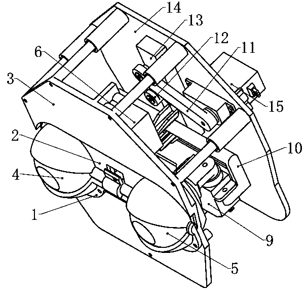
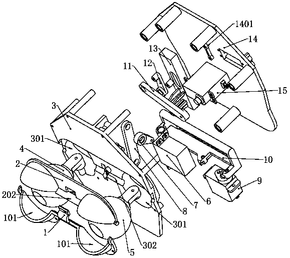
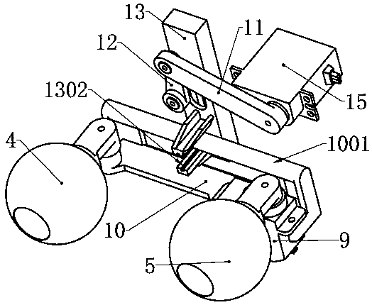
[0003] The purpose of the present invention is to provide a robot eye drive mechanism, aiming at solving the problem that the eye structure of the robot in the prior art is complex and cannot be rotated flexibly

Method used


Image

  • Bio-robot eye driving mechanism
  • Bio-robot eye driving mechanism
  • Bio-robot eye driving mechanism

Examples


Embodiment Construction

[0018] In order to make the technical problems, technical solutions and beneficial effects to be solved by the present invention clearer, further detailed description will be given below in conjunction with the accompanying drawings and embodiments. It should be understood that the specific embodiments described here are only used to explain the present invention, not to limit the present invention.

[0019] It should be noted that when an element is referred to as being “fixed” or “disposed on” another element, it may be directly on the other element or indirectly on the other element. When an element is referred to as being "connected to" another element, it can be directly connected to the other element or indirectly connected to the other element.

[0020] It is to be understood that the terms "length", "width", "top", "bottom", "front", "rear", "left", "right", "vertical", "horizontal", "top" , "bottom", "inner", "outer" and other indicated orientations or positional rel...


PUM


Abstract

The invention provides a bio-robot eye driving mechanism. The bio-robot eye drying mechanism comprises an upper eyelid, a lower eyelid, a stand, a left eyeball, a right eyeball, a steering engine, a swing rod, a connection rod, a pull rod and a ball connection rod.

Description

technical field [0001] The invention belongs to the technical field of intelligent bionic robots, in particular to an eye transmission mechanism of a bionic robot. Background technique [0002] Eyes are one of the important organs for human beings to interact with the external environment. More than 90% of the information that humans perceive the external environment is obtained through the eyes. Eye rotation is an indispensable and important feature in robot action expressions. At present, the eye expression mechanisms of intelligent robots are either complicated in structure, with many parts and inappropriate sizes; or they have insufficient degrees of freedom and cannot rotate freely like human eyeballs; or they cannot rotate around their centers and their movements are not realistic enough. Contents of the invention [0003] The purpose of the present invention is to provide a driving mechanism for the eye of a robot, aiming to solve the problem that the eye of the ro...

Claims


Application Information

Patent Timeline
IPC IPC(8): B25J11/00
CPCB25J11/0015
Inventor 徐片红黄涛
Owner 深圳市网睿科技有限公司
Learn More