
Positioning tool and positioning method for reinforcing steel bar components in bearing platform

A technology for positioning tooling and internal steel bars, which is applied in building components, building reinforcements, infrastructure engineering and other directions, and can solve the problems of offset and inability to connect the steel bars of the columns and the corresponding reserved steel bars, so as to ensure the connection of steel bars and improve the Plane positioning accuracy, the effect of reducing the offset

Pending Publication Date: 2018-11-23
SHANGHAI ROAD & BRIDGE (GRP) CO LTD
View PDF5 Cites 5 Cited by
  • Summary
  • Abstract
  • Description
  • Claims
  • Application Information

AI Technical Summary

Problems solved by technology

[0004] The technical problem to be solved by the present invention is to overcome the defect that the column steel bar of the traditional prefabricated assembled bridge and the corresponding reserved steel bar are easily offset and cannot be docked in the prior art, and to provide a Positioning tooling and positioning method of steel bar components

Method used


Image

  • Positioning tool and positioning method for reinforcing steel bar components in bearing platform
  • Positioning tool and positioning method for reinforcing steel bar components in bearing platform
  • Positioning tool and positioning method for reinforcing steel bar components in bearing platform

Examples


Embodiment Construction

[0076] The present invention is further illustrated below by means of examples, but the present invention is not limited to the scope of the examples.

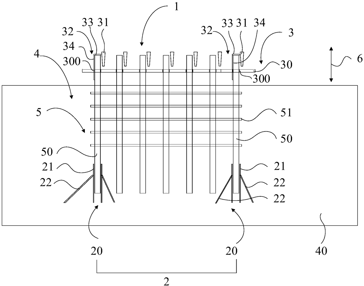
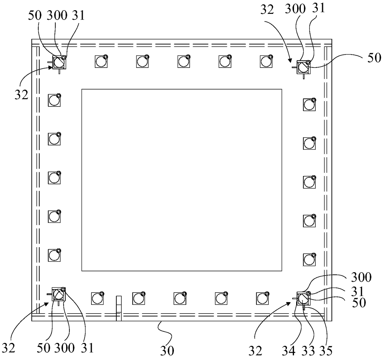
[0077] Figure 2-3 According to an embodiment of the present invention, a schematic diagram of a use state of a positioning tool for a steel bar assembly in a platform is shown. Such as Figure 2-3 As shown, the platform 4 has a cushion 40 . The steel bar assembly 5 includes a plurality of steel bars 50 and a bar support 51 . A plurality of steel bars 50 are connected to the steel bar bracket 51 to form an integral structure. Its rigidity is relatively large. A plurality of steel bars 50 are arranged at intervals and parallel to each other.

[0078] The positioning tool 1 includes a lower positioning device 2 and an upper positioning device 3 . The lower positioning device 2 is used to locate the bottoms of at least two steel bars 50 in the preset position of the cushion layer 40, so as to limit the height direction of t...


PUM


Abstract

The invention discloses a positioning tool and a positioning method for reinforcing steel bar components in a bearing platform. The positioning tool comprises a lower positioning device and an upper positioning device, wherein the lower positioning device is used for positioning the bottom parts of at least two reinforcing steel bars to the preset positions of a cushion layer; the upper positioning device comprises a positioning plate and multiple positioning parts; the positioning plate is provided with multiple positioning holes; the top part of each reinforcing steel bar penetrates throughthe corresponding positioning hole; support parts suspended on the top parts of the corresponding reinforcing steel bars are arranged in the areas, on which the at least three reinforcing steel bars are correspondingly arranged, on the positioning plate; each positioning part is inserted between each positioning hole and the corresponding reinforcing steel bar, so that the top part of each reinforcing steel bar is fixed to the corresponding positioning hole. The positioning method utilizes the positioning tool. According to the positioning tool and the positioning method for the reinforcing steel bar components in the bearing platform provided by the invention, the plane positioning accuracy among the multiple reinforcing steel bars in the bearing platform is improved, and the offset produced between a stand column reinforcing steel bar and the corresponding reinforcing steel bar in the bearing platform when the bearing platform and a stand column are in butt joint is greatly reduced or almost avoided, so that the stand column reinforcing steel bar and the corresponding reinforcing steel bar in the bearing platform are ensured to be in butt joint.

Description

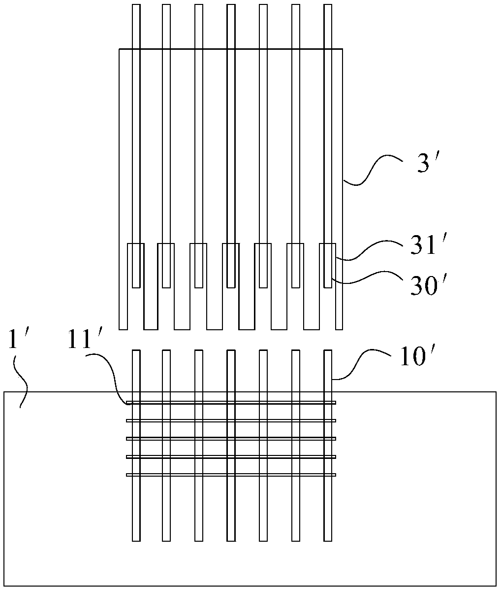
technical field [0001] The invention relates to the field of prefabricated assembled bridges, in particular to a positioning tool and a positioning method for steel bar components in caps. Background technique [0002] Prefabricated assembled viaducts are a development direction in the field of bridges in recent years. Such as figure 1 As shown, the prefabricated assembled bridge generally includes caps 1' and columns 3'. A plurality of column steel bars 30' and a plurality of grouting sleeves 31' arranged at intervals and in parallel are arranged in the column 3', and the multiple column steel bars 30' are arranged in one-to-one correspondence with the plurality of grouting sleeves 31', and each column steel bar The bottom of 30' sits within the top of the corresponding grout sleeve 31'. A reinforcing bar assembly is arranged inside the platform 1', and the reinforcing bar assembly includes a plurality of reserved reinforcing bars 10' arranged in parallel at intervals an...

Claims


Application Information

Patent Timeline
Patent Type & Authority Applications(China)
IPC IPC(8): E02D27/12E04C5/16E04C5/18
CPCE02D27/12E04C5/165E04C5/18
Inventor 魏明明贾雷刚史璐琨张政张秋柏
Owner SHANGHAI ROAD & BRIDGE (GRP) CO LTD
Learn More