Bearing drive mechanism for vehicle door system

A driving mechanism and vehicle door technology, applied in the field of rail transit doors, can solve the problems of inability to judge the locked or open state, limit the bearing capacity of the bearing driving mechanism, and require high precision of parts, so as to facilitate installation, debugging and maintenance, and improve rigidity. and the effect of carrying capacity, assuring stability and safety

Pending Publication Date: 2018-11-23
NANJING KANGNI MECHANICAL & ELECTRICAL
View PDF0 Cites 1 Cited by
  • Summary
  • Abstract
  • Description
  • Claims
  • Application Information

AI Technical Summary

Problems solved by technology

[0003] The load-bearing drive mechanism is mostly used in public transportation fields such as rail transit and buses. Since the connection between the fixed end and the load-bearing drive part uses a connecting rod, there is a transverse gap between the two during the longitudinal relative movement. The position of the driving part is shifted until one side of the load-bearing drive part is in full contact with the side of the fixed end, so that the self-aligning ball bearing installed at the end of the load-bearing drive part far exceeds the theoretical self-aligning angle of the self-aligning ball bearing, resulting in the stagnation of the bearing Sliding friction, so that the dry friction between the load-bearing drive part and the fixed end will cause excessive running resistance and cause stagnation, and will generate relatively large noise. Belts or wire ropes are often used in the mechanism to pull the active door and the driven door, which limits the load-carrying capacity of the drive mechanism, and it is impossible to judge whether the side of the linkage mechanism is locked or opened, especially when the vehicle is running. Once the towed side is out of control, there will be a great potential safety hazard; secondly, the structure is complex, the precision of the parts is high, and the weight is heavy.

Method used


Image

  • Bearing drive mechanism for vehicle door system
  • Bearing drive mechanism for vehicle door system
  • Bearing drive mechanism for vehicle door system

Examples


Embodiment Construction

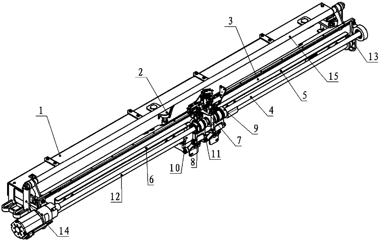
[0016] like figure 1 , the fixed frame 1 is fixed on the vehicle, the fixed frame 1 is fixedly connected with the slideway 2, and there is a drive assembly 4 used to drive the doors on both sides on the bearing transverse bracket 3, and the drive assembly 4 includes a screw rod 403, a drive motor 401 and a door control The device 402 is divided into a right locking slideway 5 and a left locking slideway 6 on both sides of the carrying horizontal bracket 3, the fixed frame 1 is fixedly connected with the left locking slideway 5 and the right locking slideway 6, and the carrying horizontal bracket 3 There is a locking mechanism 7 in the middle, the left nut assembly 8 is connected with the left sliding cylinder 10 through the linkage frame 19, the right nut assembly 9 is connected with the right sliding cylinder 11 through the linkage frame 19, the left sliding cylinder 10 is fixedly connected with the left door leaf, and the right The sliding cylinder 11 is fixedly connected wi...


PUM


Abstract

The invention discloses a bearing drive mechanism for a vehicle door system. The bearing drive mechanism comprises a fixing frame, a slideway, a bearing transverse support, a long guide column, a drive component, a locking mechanism, a left nut component, a right nut component, a left slide cylinder, a right slide cylinder, a left hanging rack and a right hanging rack and is characterized in thatthe slideway and the bearing transverse support are arranged on the fixing frame, the drive component comprises a screw, a drive motor and a door controller, the locking mechanism is arranged in the middle of the bearing transverse support, the left nut component and the right nut component sleeve the screw, the left slide cylinder and the right slide cylinder sleeve the long guide column, the left nut component is connected with the left slide cylinder through a linkage rack, the right nut component is connected with the right slide cylinder through a linkage rack, two ends of the long guidecolumn are provided with deep groove ball bearings, the deep groove ball bearings respectively roll the slide grooves of a left hanging rack and a right hanging rack, and a small roller is arranged ona mounting plate. The bearing drive mechanism is simple in structure, convenient to mount, debug and maintain, small in operation resistance, stable in operation, small in operation noise and high inrigidity, and the state of the drive mechanism can be monitored.

Description

technical field [0001] The invention relates to the field of rail transit doors, in particular to a bearing drive mechanism for a vehicle door system. Background technique [0002] The load-bearing drive mechanism of the existing vehicle door system is mainly composed of three parts: load-bearing, driving and locking. The motor drives the screw rod to drive the nut assembly arranged on the screw rod to reciprocate, and then drives the controlled object connected with the nut assembly. sports. [0003] The load-bearing drive mechanism is mostly used in public transportation fields such as rail transit and buses. Since the connection between the fixed end and the load-bearing driving part adopts a connecting rod, there is a lateral gap between the two during the longitudinal relative movement. During the operation, the load is caused by the action of inertia. The position of the drive part is shifted until one side of the load-bearing drive part is in complete contact with th...

Claims


Application Information

Patent Timeline
Patent Type & Authority Applications(China)
IPC IPC(8): E05F15/652E05F15/657E05D13/00E06B7/28B61D19/02
CPCE05F15/652B61D19/005B61D19/02E05D13/00E05F15/657E06B7/28
Inventor 吴翔郭显鹏左丽飞霍旭东龚丽琴吕宾宾邱爽
Owner NANJING KANGNI MECHANICAL & ELECTRICAL
Why Eureka
Try Eureka