Input shaft braking system and method for reverse gear

A technology of braking system and input shaft, applied in the direction of components with teeth, transmission control, belt/chain/gear, etc., can solve the problems of high cost and complicated design, and achieve the effect of simple and cheap design

Active Publication Date: 2021-08-03
SCHAEFFLER TECH AG & CO KG
View PDF7 Cites 0 Cited by
  • Summary
  • Abstract
  • Description
  • Claims
  • Application Information

AI Technical Summary

Problems solved by technology

The design is very complicated and the cost is very high

Method used


Image

  • Input shaft braking system and method for reverse gear
  • Input shaft braking system and method for reverse gear
  • Input shaft braking system and method for reverse gear

Examples


Embodiment Construction

[0037] Exemplary embodiments of the present invention are described below with reference to the accompanying drawings. It should be understood that these specific descriptions are only used to teach those skilled in the art how to implement the present invention, but are not intended to exhaust all possible ways of the present invention, nor are they intended to limit the scope of the present invention.

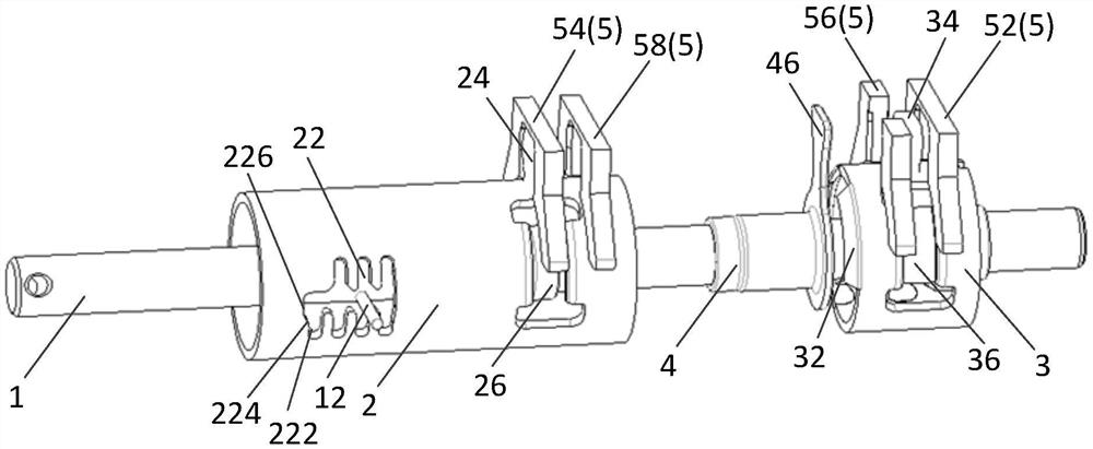
[0038] In the following, for the convenience of explanation, the figure 2 The direction of the axis of the shift shaft 1 is called "axial direction", the direction perpendicular to the axial direction is called "radial direction", and the direction around the axial direction is called "circumferential direction".

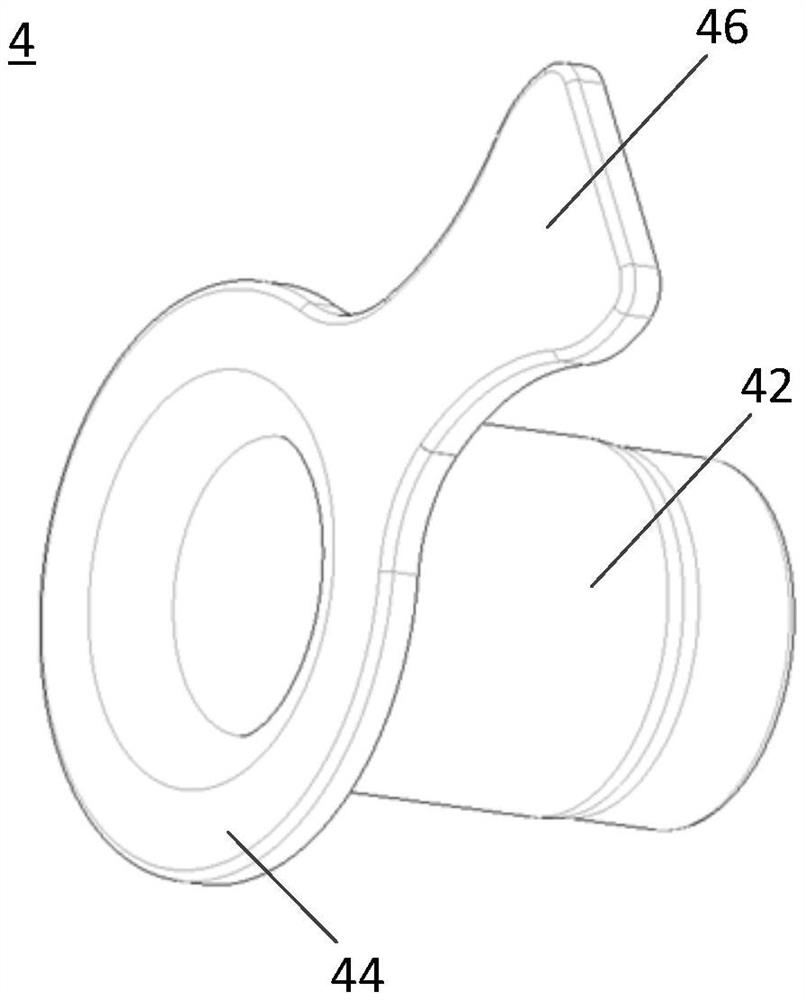
[0039] The following will refer to Figure 2-Figure 5 The input shaft brake system for the reverse gear on the shift tower of the present invention will be described. figure 2 is a perspective view showing a shift system according to an embodiment of the presen...


PUM


Abstract

An input shaft braking system and method for reverse gear are provided, which are simple and easy to implement and low in cost, and are used for quickly engaging the reverse gear. The input shaft braking system for reverse gear includes: a plurality of fork brackets, the plurality of fork brackets include reverse gear brackets and non-reverse gear brackets; and brake fingers, the brake fingers configured to engage and disengage the non-reverse yoke, the reverse yoke, the non-reverse yoke, and the brake finger are arranged so that during reverse operation , before the reverse gear bracket drives the reverse gear shift fork to move to the position where the reverse gear meshes with the input shaft transmission gear, the brake finger first engages with the non-reverse gear bracket to realize non-reverse gear The semi-synchronous braking of the gear is then disengaged.

Description

technical field [0001] The present invention relates to a gear shifting system and, in particular, to an input shaft braking system and method for reverse gearing. Background technique [0002] figure 1 A form of gear arrangement for a manual transmission of an automobile is shown. From figure 1 It can be seen in the figure that the seven gears from ① to R (reverse) are divided into four gear groups. Specifically, ① and ② are in one group, ③ and ④ are in one group, ⑤ File and ⑥ file are a group, and R file is a group alone. [0003] When performing a gear shifting operation, firstly, the shift handle needs to be shifted to the neutral position of the gear group where the target gear is located, and then the handle is shifted to the target gear. For example, when it is necessary to change from ② to ③, the driver needs to first turn the handle from ② to the neutral position between ① and ②, and then turn the handle to the position between ③ and ④. The neutral position, an...

Claims


Application Information

Patent Timeline
Patent Type & Authority Patents(China)
IPC IPC(8): F16H63/30
CPCF16H63/302F16H2063/3076F16H2063/3083F16H63/20
Inventor 李海涛吉裕兰
Owner SCHAEFFLER TECH AG & CO KG
Why Eureka
Try Eureka