Supercharge Your Innovation With Domain-Expert AI Agents!

Manufacturing method of sliding bracket for steam pipeline, and sliding bracket

A steam pipeline and sliding support technology, which is applied in the direction of pipeline supports, pipes/pipe joints/pipe fittings, mechanical equipment, etc., can solve the problems of low efficiency and complex production of sliding supports, and achieve the effects of simple production, reduced construction period and improved production

Inactive Publication Date: 2018-11-23
MCC5 GROUP CORP SHANGHAI
View PDF5 Cites 0 Cited by
  • Summary
  • Abstract
  • Description
  • Claims
  • Application Information

AI Technical Summary

Problems solved by technology

[0004] Therefore, the technical problem to be solved by the present invention is to overcome the problem of low efficiency due to the complicated manufacture of the sliding support for small-diameter steam pipes in the prior art, so as to provide a steam pipe sliding frame with simple manufacture and high construction efficiency. Manufacturing method of bracket and sliding bracket

Method used


Image

  • Manufacturing method of sliding bracket for steam pipeline, and sliding bracket
  • Manufacturing method of sliding bracket for steam pipeline, and sliding bracket

Examples


Embodiment 1

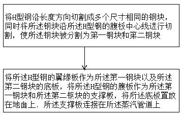
[0020] Such as figure 1 and figure 2 As shown, the present embodiment provides a method for manufacturing a sliding bracket for a steam pipe, which is placed under the steam pipe 10, and includes the following steps: Step S1: Cut the H-shaped steel into multiple steel blocks of the same size along the length direction, and at the same time Cutting the steel block along the web centerline of the H-shaped steel, so that the steel block is divided into a first steel block and a second steel block; Step S2: using the flange plate of the H-shaped steel as the The bottom plate 21 of the first steel block and the second steel block, the web of the H-shaped steel is used as the support plate 22 of the first steel block and the second steel block, and the bottom plate 21 is placed On the ground, the support plate 22 is connected to the steam pipe 10 .

[0021] The steam pipeline sliding support in this embodiment is placed under the steam pipeline 10, including the following steps: ...

Embodiment 2

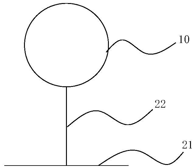
[0025] This embodiment provides a sliding bracket, which is manufactured using the manufacturing method described in Embodiment 1, such as figure 2 As shown, it includes a bottom plate 21 and a support plate 22 above the bottom plate 21 , wherein the bottom plate 21 and the support plate 22 are integrally formed, and the support plate 22 is fixed on the steam pipe 10 .

[0026] The sliding bracket in this embodiment includes a bottom plate 21 and a support plate 22 above the bottom plate 21, wherein the bottom plate 21 and the support plate 22 are integrally formed, and the support plate 22 is fixed on the steam pipe 10 In fact, due to the simple production, it can greatly improve the installation efficiency, thereby helping to reduce the construction period of the entire project.

[0027] The bottom plate 21 is fixed on the embedded parts, and the flatness can be ensured by the embedded parts. The height direction of the support plate 22 is perpendicular to the length direc...


PUM


Abstract

The invention relates to a manufacturing method of a sliding bracket for a steam pipeline, and the sliding bracket. The sliding bracket is placed below the steam pipeline; the manufacturing method ofthe sliding bracket comprises the following steps of: cutting H-shaped steel into a plurality of steel blocks which are the same in size in the length direction; simultaneously cutting each steel block along the center line of a web of the H-shaped steel to form a first steel block and second steel block; taking a flange plate of the H-shaped steel as a base plate of the firs steel block and the second steel block; taking the web of the H-shaped steel as a supporting plate of the first steel block and the second steel block; placing the base plate on the ground; and connecting the supporting plate to the steam pipeline. The manufacturing method provided by the invention can get materials conveniently and realizes simple manufacturing, thereby improving the construction efficiency.

Description

technical field [0001] The invention relates to the technical field of conveying pipelines, in particular to a method for manufacturing a steam pipeline sliding bracket and the sliding bracket. Background technique [0002] In metallurgical construction projects, during the operation of the steam pipeline, in addition to axial movement, displacement in other directions of the pipeline is not expected. In order to reduce the friction of the steam pipeline during operation and make the steam pipeline run more smoothly, sliding structures are usually used as support points and sliding points. [0003] The design and manufacture structure of the traditional steam pipeline sliding bracket is as follows: the sliding surface of the bottom plate is a square steel plate, a short tube is used as a support tube above the center of the steel plate, and the upper part of the support tube is an arc-shaped steel plate. The arc-shaped steel plate is directly connected with the steam pipeli...

Claims


Application Information

Patent Timeline
IPC IPC(8): F16L3/00
CPCF16L3/00
Inventor 刘威倪俣郭强刘佳秦一中
Owner MCC5 GROUP CORP SHANGHAI
Features
  • R&D
  • Intellectual Property
  • Life Sciences
  • Materials
  • Tech Scout
  • Unparalleled Data Quality
  • Higher Quality Content
  • 60% Fewer Hallucinations
Learn More