A bridge monitoring device

A technology for monitoring devices and bridges, which is applied in the direction of measuring devices, optical devices, instruments, etc., can solve the problems of inconvenient large-scale bridge monitoring, errors in data test results, and heavy layout workload, so as to accurately evaluate the force and damage of bridges situation, increasing temperature compensation, and optimizing the effect of position

Active Publication Date: 2020-08-04
四川衡兴泰工程技术咨询服务有限公司
View PDF9 Cites 0 Cited by
  • Summary
  • Abstract
  • Description
  • Claims
  • Application Information

AI Technical Summary

Problems solved by technology

[0003] In the prior art of bridge deflection monitoring, the publication number is CN206160926U "a relatively vertical and unique measurement system between adjacent hollow slabs of a hollow slab bridge", by setting a plurality of measuring devices on the measured object, each measuring device Including displacement sensors and information emission collection and processing devices to monitor the force of the hollow slab veneer, so as to monitor the bridge; in the actual bridge monitoring, the measured bridges are usually kilometer-level units, the application of the above devices will make The manpower and material resources for bridge monitoring increase, which is not convenient for the monitoring of large bridges
At the same time, the "Bridge Deflection Monitoring System" with the publication number CN101050992A replaces the monitoring displacement sensor with a variety of monitoring suspenders, but in essence it still needs to set more suspender monitoring points along the length of the bridge. The layout of the bridge requires a lot of work. On the other hand, in this application, the scale value of the vertical side pole is obtained through a camera or a telescope. The operation is complicated, and it is more dependent on human subjectivity, which is not convenient for accurate data recording.
[0004] At the same time, the existing technology is not very applicable to the monitoring of bridge strain or displacement, and the sensor structure is relatively simple, without considering the influence of temperature on the sensor test results, which will cause large errors in the data test results due to temperature changes, and it is difficult to meet the engineering requirements. testing requirements, does not have a significant advantage

Method used


Image

  • A bridge monitoring device
  • A bridge monitoring device
  • A bridge monitoring device

Examples


Embodiment Construction

[0013] The principles and features of the present invention are described below in conjunction with the accompanying drawings, and the examples given are only used to explain the present invention, and are not intended to limit the scope of the present invention.

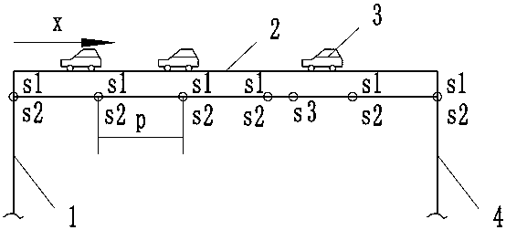
[0014] Such as figure 1 As shown, the bridge 2 has a first bridge support 1 and a second bridge support 4 arranged at both ends, a load 3 is arranged on the bridge 2, and a plurality of identical strain sensors s1 are arranged on the bridge 2, and the strain sensors are gratings A plurality of grating strain sensors s1 are installed on the bridge to be measured at equal or non-equal intervals, and a grating temperature compensation sensor s3 is also installed separately, and the grating temperature compensation sensor s3 is set at the position where the temperature of the bridge is average , preferably set at a position one-third of the length from one end of the bridge, the data acquisition device is connected to t...


PUM


Abstract

The invention relates to a bridge monitoring device. The device comprises a plurality of identical measuring sensors arranged on a bridge, and a plurality of grating strain sensors and displacement sensors are arranged at equal intervals on the to-be-tested bridge, and a grating temperature compensation sensor is arranged at a part of the average temperature of the bridge. A data acquisition device is connected with the grating strain sensors, the displacement sensors and the grating temperature compensation sensor in a wired or wireless manner, and the data acquisition device collects the changes of the center wavelengths of the strain sensors during different bridge loads, and transmits the collected data to a data processing device. The data processing device calculates the strain and / or displacement of the bridge based on the collected data to determine whether the bridge is damaged or not according to the strain and / or deflection of the bridge. The device saves a monitoring sensor, reduces the cost, and avoids the data redundancy of collection.

Description

technical field [0001] The invention relates to the technical field of bridge accessories, in particular to a monitoring device for bridge deflection using a strain sensor. Background technique [0002] With the development of my country's economy and the improvement of people's living standards, people's demand for transportation is developing in a faster and more efficient direction. Therefore, many large-scale bridge constructions are planned in the national engineering construction, especially the construction of high-speed rail transit. Due to It needs to meet the high train speed and running stability. A large number of bridges and tunnels need to be planned in the line to further increase the bridge-to-tunnel ratio of the entire line. These bridges are constantly affected by temperature, The erosion of the external environment such as wind and sand, as well as the long-term repeated action of vehicle loads and vehicle impacts, and the impact of natural disasters such as...

Claims


Application Information

Patent Timeline
Patent Type & Authority Patents(China)
IPC IPC(8): G01B11/16
CPCG01B11/16
Inventor 程克玲罗化军吴庆
Owner 四川衡兴泰工程技术咨询服务有限公司
Why Eureka
Try Eureka