An optical fiber coating device with a start-up auxiliary function

A technology of coating device and auxiliary function, applied in the field of optical fiber coating device, can solve the problems of optical fiber coating outer diameter fluctuation, optical fiber processing scrap, difficult to control, etc., to reduce optical fiber scrap, reduce scrap, improve qualification rate and production The effect of efficiency

Active Publication Date: 2022-01-11
普利技术潜江有限公司 +1
View PDF0 Cites 0 Cited by
  • Summary
  • Abstract
  • Description
  • Claims
  • Application Information

AI Technical Summary

Problems solved by technology

[0003] The existing optical fiber drawing coating device is mainly suitable for the needs of high-speed optical fiber drawing, but in the initial stage of optical fiber drawing, because the drawing speed is low, the temperature of the bare optical fiber before coating is low, after the resin coating is applied by the coating device, the optical fiber The outer diameter of the coating is too large and the fluctuation is difficult to control during this low-speed speed-up stage. Most of the coatings exceed the standard and cause the fiber to be scrapped. It takes a period of time to reach the normal coating stage, resulting in the fiber at the beginning of fiber drawing. Processing and scrapping

Method used


Image

  • An optical fiber coating device with a start-up auxiliary function
  • An optical fiber coating device with a start-up auxiliary function
  • An optical fiber coating device with a start-up auxiliary function

Examples


Embodiment Construction

[0018] The present invention will be further described below in conjunction with the accompanying drawings and embodiments.

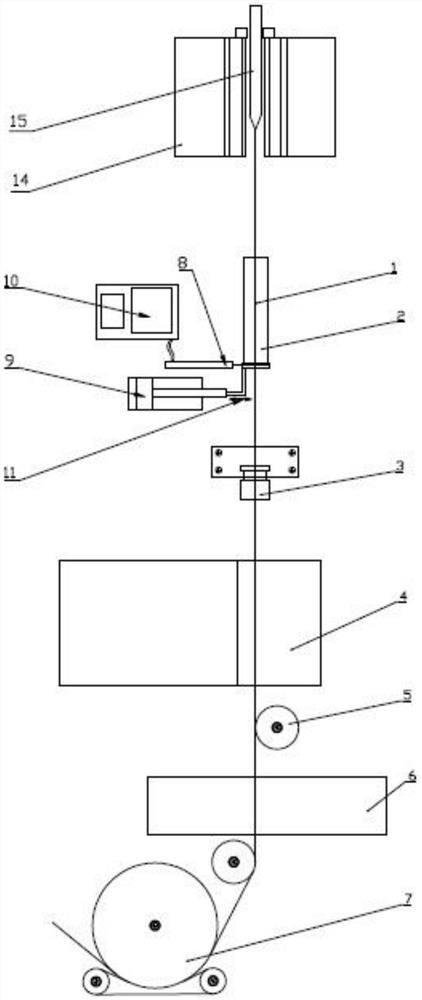
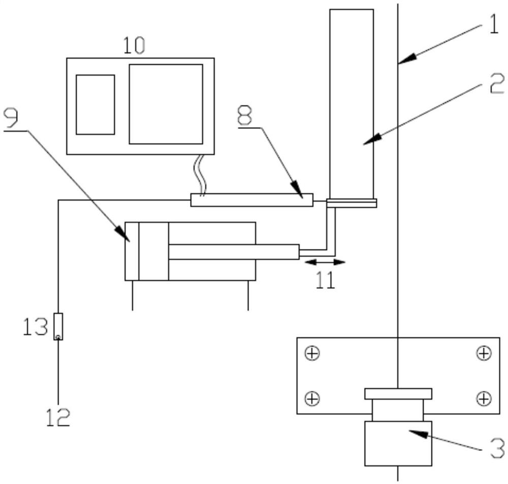
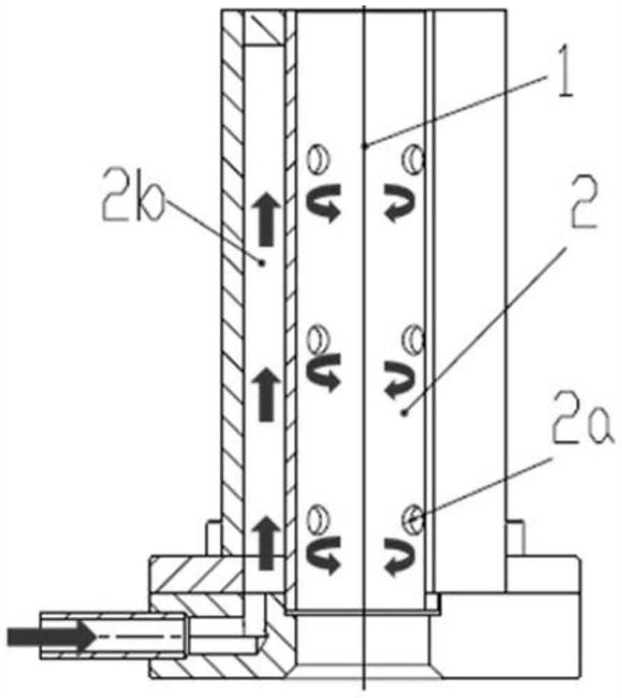
[0019] An example of the present invention is figure 1 As shown, it includes a coater 3, an ultraviolet curing device 4, a measuring device 6 and a traction mechanism 7 arranged sequentially below the drawing outlet of the wire drawing furnace 14, and a guide wheel is arranged between the ultraviolet curing device, the measuring device and the traction mechanism 5. Between the drawing outlet of the drawing furnace and the coater, an optical fiber auxiliary heating device is provided relative to the drawing track of the optical fiber 1. The auxiliary heating device includes a heating tube 2 and a hot air source connected to the heating tube. The heating The tube wall has a hollow airtight ring cavity 2b, and the inner wall of the hollow airtight ring cavity is evenly distributed with air outlet holes 2a along the upper, lower and circumferential directio...


PUM


Abstract

The invention relates to an optical fiber coating device with a start-up auxiliary function, which includes a coater, an ultraviolet curing device and a traction mechanism arranged sequentially below the wire drawing outlet of the wire drawing furnace, and is characterized in that the wire drawing outlet of the wire drawing furnace and the coater An optical fiber auxiliary heating device is arranged relative to the optical fiber pulling track. The invention heats the bare optical fiber at the initial stage of wire drawing by setting an auxiliary optical fiber heating device, which increases the temperature compensation of the bare optical fiber, enables the coating layer to meet the standard, effectively reduces the scrapped optical fiber at the initial stage of wire drawing, and optimizes the speed-up at the beginning of wire drawing The processing process of optical fiber in the first stage, thereby improving the qualification rate and production efficiency of optical fiber drawing. The invention has the advantages of simple structure, convenient use and operation, free movement in and out, high reliability, fully meets the high temperature heating of the bare optical fiber at the initial stage of drawing, matches the temperature of the coating device and the speed of the drawing device, and rapidly increases the drawing speed.

Description

technical field [0001] The invention relates to an optical fiber coating device with a starting auxiliary function, belonging to the technical field of optical fiber manufacturing equipment. Background technique [0002] The optical fiber is made of glass optical fiber preform rods melted and drawn at high temperature. During the fiber drawing process, the glass optical fiber preform rods are heated and softened in the drawing furnace, and the lower end taper becomes molten. Under the action of traction, the glass fiber filaments are formed through viscous flow. , the glass filaments pass through functional units such as high-temperature quenching, rapid cooling, resin coating, ultraviolet curing, and pulling devices in sequence to form a finished optical fiber coated with a resin coating layer. During the above optical fiber drawing process, the diameter of the glass optical fiber and the thickness of the resin coating layer are strictly regulated and controlled in order to...

Claims


Application Information

Patent Timeline
Patent Type & Authority Patents(China)
IPC IPC(8): C03C25/12C03C25/105
CPCC03C25/12C03C25/105
Inventor 杨懿王杨吕超王涛
Owner 普利技术潜江有限公司
Why Eureka
Try Eureka