
a protective device

A protection device and mounting ring technology, applied in the field of sensors, can solve the problems of increased cost of input sensors, violation of cost of use, and reduction of failure cycles.

Active Publication Date: 2020-10-02
GUIYANG BOSOR TECH
View PDF5 Cites 0 Cited by
  • Summary
  • Abstract
  • Description
  • Claims
  • Application Information

AI Technical Summary

Problems solved by technology

For example, in the application of measuring rainwater accumulation areas, it cannot be guaranteed that the area where the liquid level is measured is in a constant environmental state with or without water for a long time
At this time, if a low-cost contact liquid level sensor is used, the sensor will face problems such as accelerated corrosion and oxidation process caused by environmental changes, and a sharp decrease in failure cycle.
The use of non-contact sensors will bring uncontrollable cost problems for a large number of deployments
In order to solve this problem, the applicant found in the process of studying this application that the existing technology will improve the production process and materials of the submersible sensor to meet the use requirements, but this will increase the cost of the submersible sensor. Goes against the original intention of using contact sensors such as drop-in sensors to reduce the cost of use

Method used


Image

  • a protective device
  • a protective device
  • a protective device

Examples


Embodiment Construction

[0024] In order to make the purpose, technical solutions and advantages of the embodiments of the present invention clearer, the technical solutions in the embodiments of the present invention will be clearly and completely described below in conjunction with the drawings in the embodiments of the present invention. Obviously, the described embodiments It is a part of embodiments of the present invention, but not all embodiments. The components of the embodiments of the invention generally described and illustrated in the figures herein may be arranged and designed in a variety of different configurations.

[0025] Accordingly, the following detailed description of the embodiments of the invention provided in the accompanying drawings is not intended to limit the scope of the claimed invention, but merely represents selected embodiments of the invention. Based on the embodiments of the present invention, all other embodiments obtained by persons of ordinary skill in the art wi...


PUM


Abstract

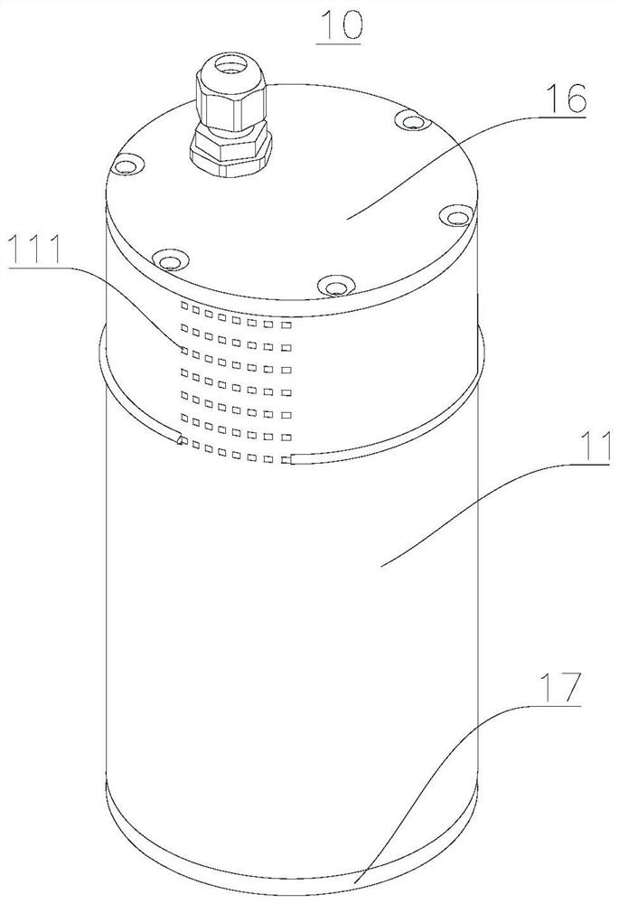
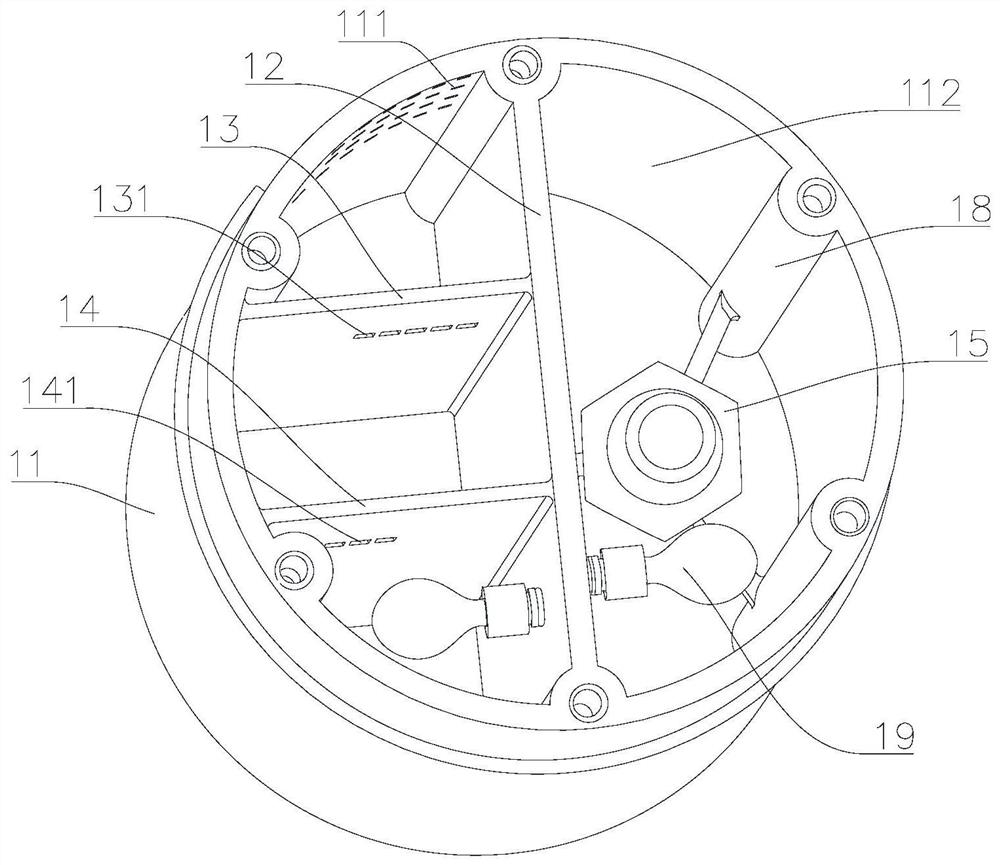
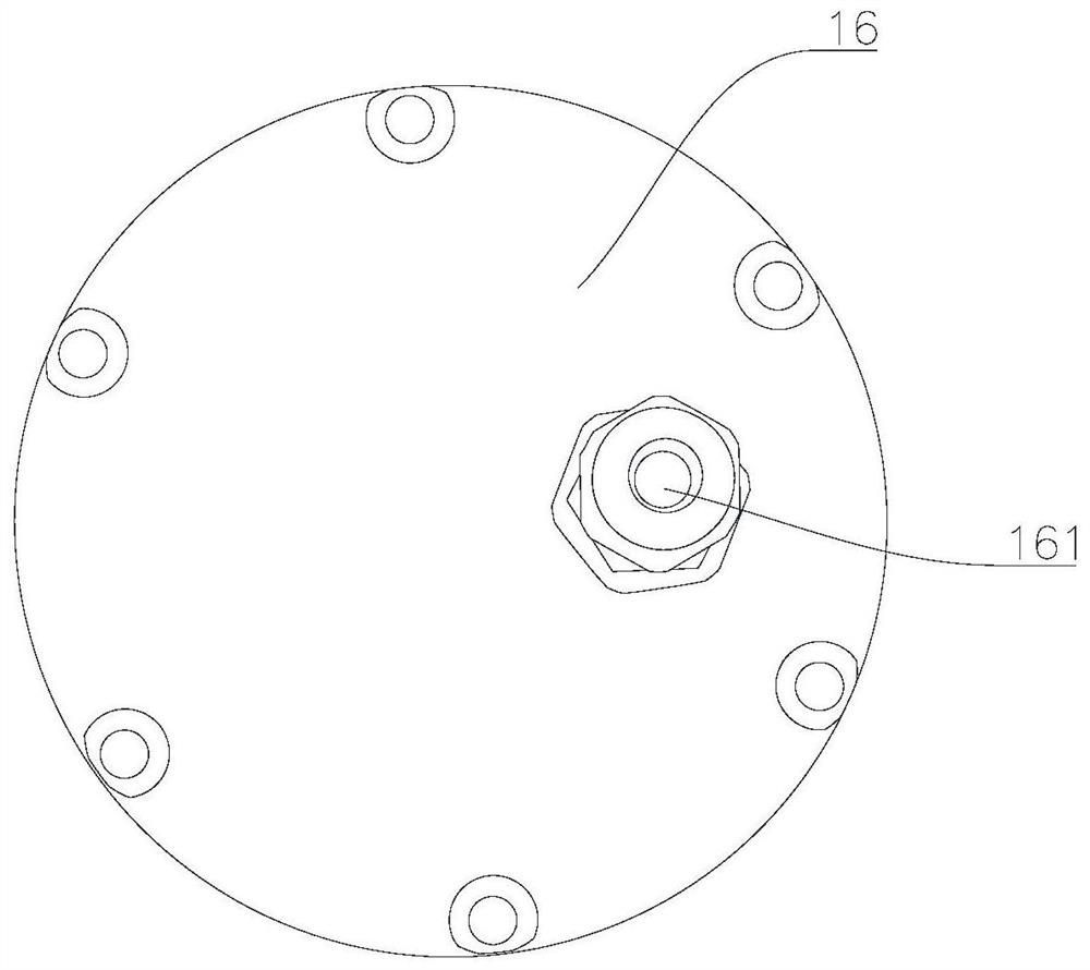
The invention relates to a protecting device, and belongs to the technical field of sensors. The protecting device comprises a housing, a first sealing cover and two sealing members. An opening is formed in one end of the housing, the opening extends from one end of the housing to the other end of the housing to form an accommodation cavity, the housing is internally provided with a first baffle plate, the accommodation cavity is divided into a first cavity and a second cavity by the first baffle plate, the first cavity is internally provided with an installing member, a first screw hole and asecond screw hole are formed in the first baffle plate, a sealing member comprises sealing guiding tubes and a sealing air bag, one end of the sealing guiding tube is connected with the sealing air bag, one sealing guiding tube is connected with the first screw hole, the sealing air bag is located in the first cavity, the other sealing guiding tube is connected with the second screw hole, the sealing air bag is located in the second cavity, a filtering hole is formed in the part, close to the opening end, of the housing, and the filtering hole allows the second cavity to be communicated withthe exterior of the housing. By means of the protecting device, a liquid level sensor can be completely separated from the environment, and the measuring function of the liquid level sensor is not influenced.

Description

technical field [0001] The invention belongs to the technical field of sensors, and in particular relates to a protection device. Background technique [0002] At present, the liquid level sensors used can be roughly divided into two categories: one is contact type, including: single flange static pressure / double flange differential pressure liquid level sensor, float type liquid level sensor, magnetic liquid level sensor, input Type liquid level sensor, electric inner float liquid level sensor, electric float liquid level sensor, capacitive liquid level sensor, magnetostrictive liquid level sensor, servo liquid level sensor, etc. The second type is non-contact type, which is divided into ultrasonic liquid level sensor, radar liquid level sensor and so on. Contacting liquid level sensors usually have lower cost applications. Non-contact liquid level sensors usually have better environmental adaptability, but the application cost is also higher. [0003] For some applicati...

Claims


Application Information

Patent Timeline
Patent Type & Authority Patents(China)
IPC IPC(8): G01F23/00
CPCG01F23/00
Inventor 李昆丁勇田建勇
Owner GUIYANG BOSOR TECH
Learn More