Differential pressure generator

a generator and differential technology, applied in the direction of machines/engines, secondary cells servicing/maintenance, electric generator control, etc., can solve the problem that the rotational speed of the turbine is limited only by the bearing, and achieve the effect of low cost and high reliability

Active Publication Date: 2010-06-03
PARKER INTANGIBLES LLC
View PDF14 Cites 9 Cited by
  • Summary
  • Abstract
  • Description
  • Claims
  • Application Information

AI Technical Summary

Benefits of technology

[0011]The present invention provides an integrated turbine generator which has all elements of the electrical system separated from the turbine and rotor by a static seal pressure boundary. Electrical power is generated through this boundary. This approach is simple, low cost and highly reliable. The pressurized media also does not circulate in close proximity to the rotating magnets of the generator turbine or the support bearing.

Problems solved by technology

The absence of a dynamic seal removes any rotational speed restriction imposed by the presence of a dynamic seal since higher turbine speeds will wear dynamic seals faster.
In addition, by not having a dynamic seal, the rotational speed of the turbine is limited only by the bearing.

Method used


Image

  • Differential pressure generator
  • Differential pressure generator
  • Differential pressure generator

Examples


Embodiment Construction

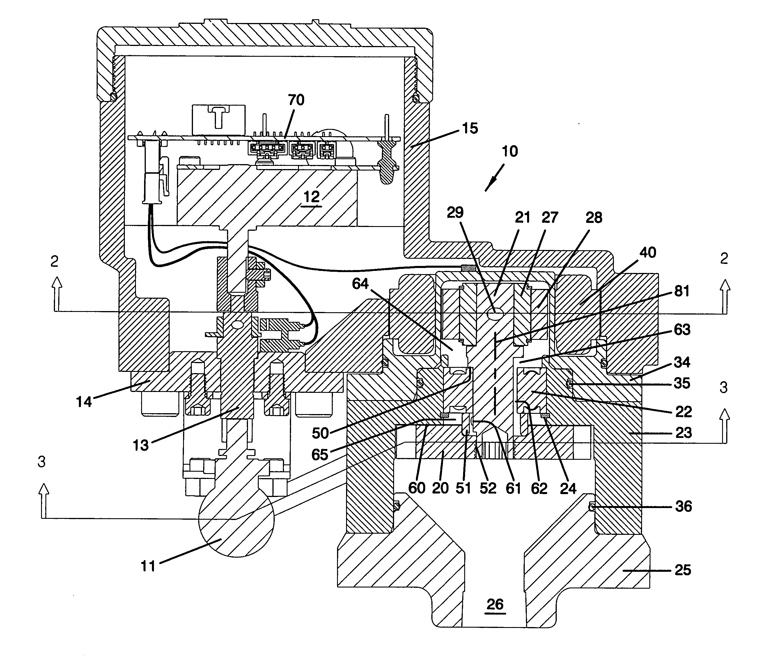
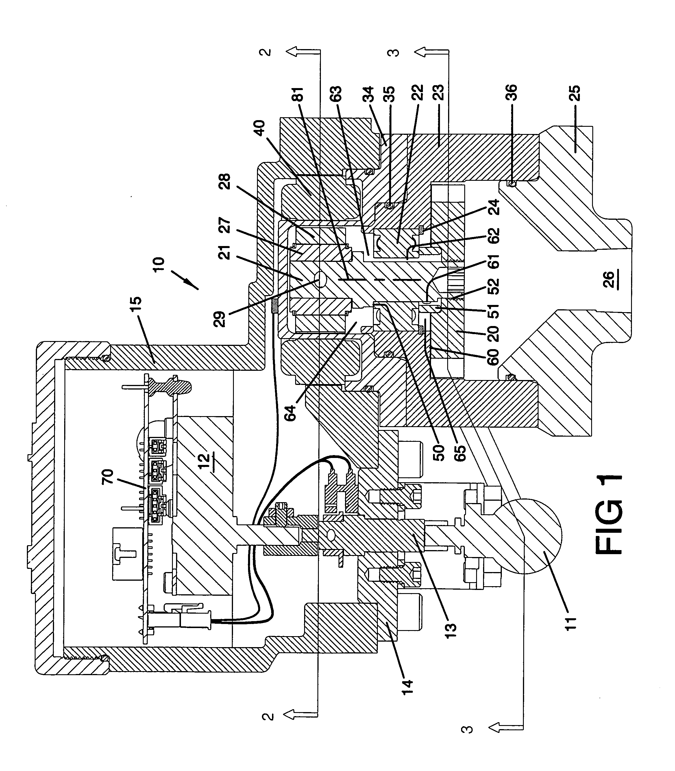
[0020]The integrated turbine generator assembly 10 is comprised of a flow control valve 11 connected to valve control motor 12 by a motor control shaft 13. Valve 11 is mounted to mounting plate 14 attached to generator housing 15. Mounting plate 14 further supports and guides motor control shaft 13, which connects to both valve 11 and control motor 12.

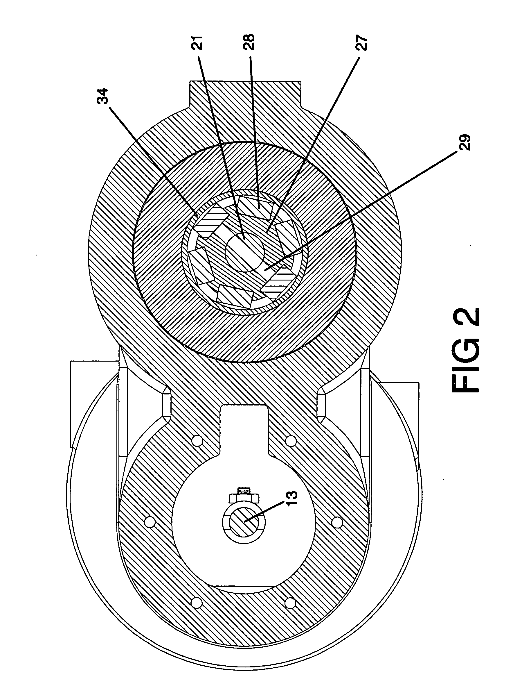
[0021]Turbine 20 is attached to rotor shaft 21 which is supported by bearing 22 within turbine housing 23. The inside race of bearing 22 is trapped between shoulder 50 on shaft 21 and a sleeve shaped turbine rotor spacer 51 which is brought into contact with turbine rotor 20 when screwed onto shaft 21 at thread 52. The outside race of bearing 22 is mounted in turbine housing 23 and secured with snap ring 24. Pressure is balanced across bearing 22 as it passes through gap 60 between turbine rotor 20 and turbine housing 23. Pressure then enters cavity 65 and passes through turbine spacer 51 via drilled through port 61. Pressure may then ...


PUM


Abstract

An electrical generator (10) powered by fluid pressure in a flow line includes a turbine housing (23) and control valve (11). The turbine housing houses a rotor (29) and a plurality of turbine blades (33) which are rotated by fluid passing from the flow line through the turbine housing. A bearing (22) within the turbine housing guides rotation of the rotor, and supports a plurality of magnets (28). Cap member (23) is sealed to the turbine housing, and a stator (40) external of the cap member generates electricity in response to a plurality of rotating magnets.

Description

FIELD OF THE INVENTION[0001]The invention relates generally to an integrated turbine generator, such as used in a generator and battery charge control system, using the pressure differential typically found in natural gas production and transmission systems.BACKGROUND OF THE INVENTION[0002]The natural gas production and transmission industry routinely wastes significant amounts of energy that could be put to economical and environmentally friendly use for the production of electrical energy. The need for electric power at the well site, compressor stations, downstream city gate and neighborhood distribution stations is well known. Flow measurement, equipment status, valve actuation, emission control and communication systems all require different but typically small amounts of electrical energy to operate. Even when grid electric power is available, commercial electrical power may not be desirable to use due to setup and permitting costs. In these and remote situations where grid po...

Claims


Application Information

Patent Timeline
Patent Type & Authority Applications(United States)
IPC IPC(8): H02J7/32H02K7/18H02P9/04
CPCF01D1/026H02K7/1823H02K7/20F05D2220/62H02K11/0094H02K16/00H02P9/02H02K11/0073H02K11/33
Inventor NIMBERGER, SPENCER M.
Owner PARKER INTANGIBLES LLC
Why Eureka
Try Eureka