A sample preparation method for graphite optical microstructure characterization

A technology for optical microscopy and sample preparation, which is applied in the preparation, sampling, and scientific instruments of samples for testing. It can solve the problems of poor sample grinding and polishing effects, improve the surface quality of samples, compact texture, and improve surface smoothness. degree of effect

Active Publication Date: 2020-12-08
SINOSTEEL NEW MATERIAL ZHEJIANG
View PDF33 Cites 0 Cited by
  • Summary
  • Abstract
  • Description
  • Claims
  • Application Information

AI Technical Summary

Problems solved by technology

[0005] The purpose of the present invention is to address the deficiencies of the prior art and provide a sample preparation method for graphite optical microstructure characterization. After the graphite material and the gas in the mixed resin are discharged through negative pressure exhaust, the graphite material After mixing and solidifying with the mixed resin, the sample is fixed horizontally by horizontal positioning and clamping, and then the sample is subjected to multi-stage surface grinding and polishing with variable ballast force to achieve a sample to be analyzed with compact texture, smooth surface and clear texture Manufactured to solve the technical problem of poor sample grinding and polishing effect existing in the prior art

Method used


Image

  • A sample preparation method for graphite optical microstructure characterization
  • A sample preparation method for graphite optical microstructure characterization
  • A sample preparation method for graphite optical microstructure characterization

Examples


Embodiment 1

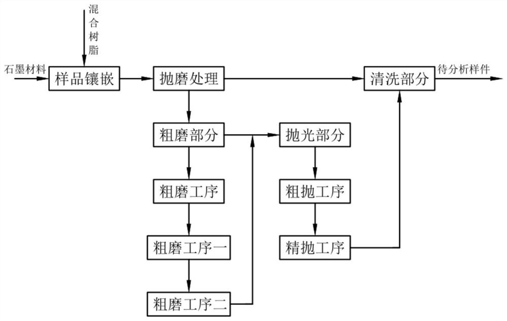
[0045] According to the drawings in the manual figure 1 A sample preparation method for optical microstructure characterization of graphite in this example is described.

[0046] A sample preparation method for graphite optical microstructure characterization, comprising the following steps:

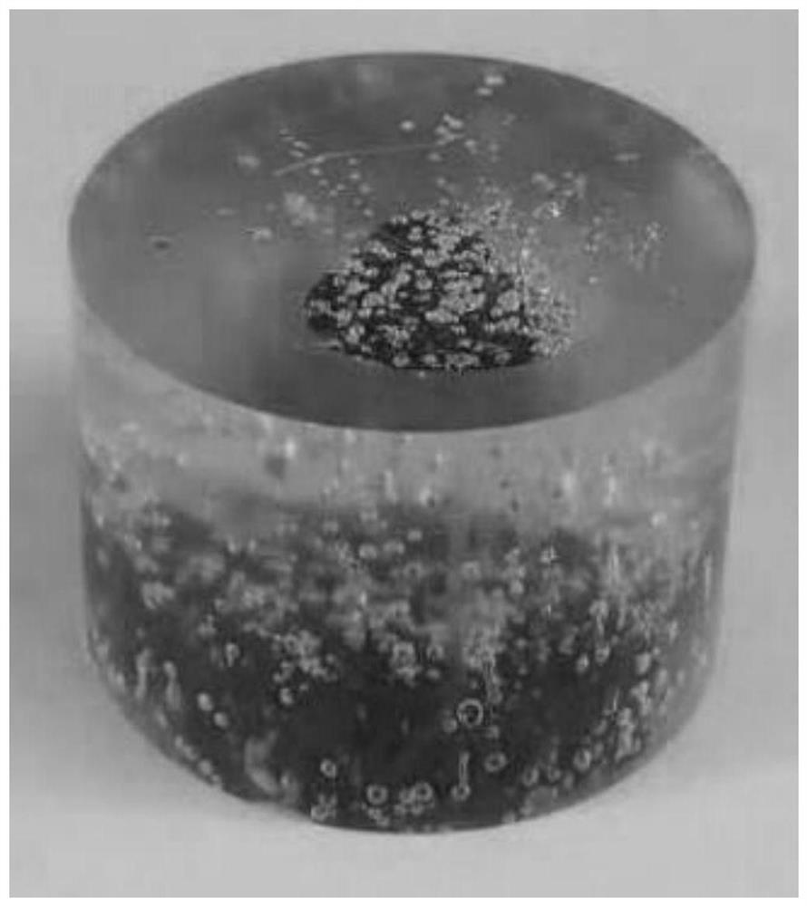
[0047] (a) Sample inlay, after the graphite material and the mixed resin are exhausted by vacuuming through the inlay equipment, the graphite material and the mixed resin are mixed by pouring to form a compact and solid sample to be ground;

[0048] (b) Grinding and polishing treatment, the plurality of samples to be ground formed by the step (a) are clamped on the sample holder on the grinding and polishing equipment in a horizontal positioning manner, and the samples are respectively pressed in an elastic pressurized manner through the loading plate. While the sample on the fixture is being pressurized, the sample is subjected to multi-stage grinding and polishing treatment through th...

Embodiment 2

[0057] Wherein, the same or corresponding parts as those in the first embodiment adopt the reference numerals corresponding to the first embodiment. For the sake of simplicity, only the differences from the first embodiment are described below; the difference between the second embodiment and the first embodiment is that : The step (b) also includes a coarse grinding part, applying a ballast elastic force of 10-20N to the sample to be ground by the loading disc in a downward pressure mode, and adopting a SiC sandpaper grinding disc with a mesh number of 300-2500 to cooperate with the sample fixture Grinding the surface of the sample to be polished in a rotational friction manner with a differential speed of 100-200 rpm to form a sample to be thrown with a surface finish Ra: 5-40 μm.

[0058] Specifically, the rough grinding part includes:

[0059] In the coarse grinding process, a ballast elastic force of 10-20N is applied to the sample to be ground by the loading disc in a do...

Embodiment 3

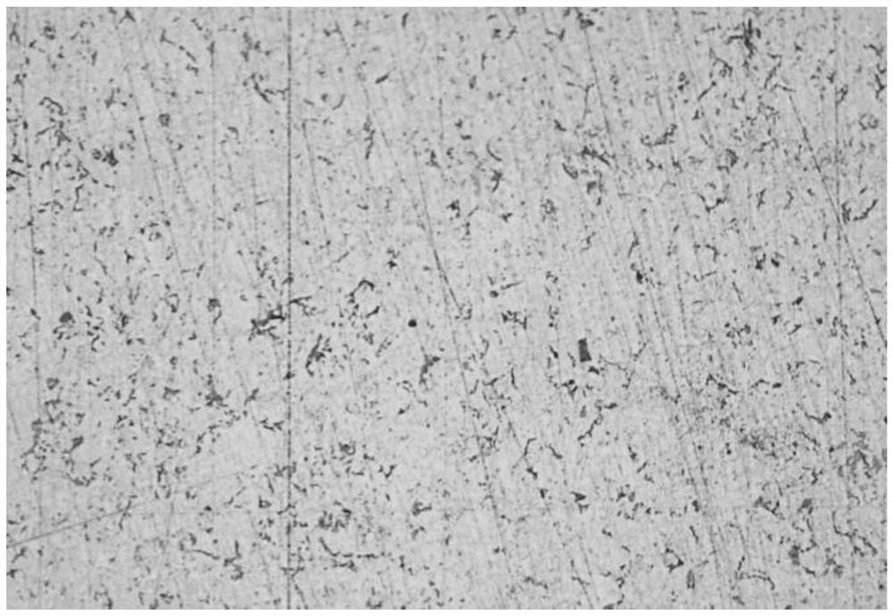
[0063] Wherein, the same or corresponding parts as those in Embodiment 2 adopt the reference numerals corresponding to Embodiment 1. For the sake of simplicity, only the differences from Embodiment 2 are described below; the difference between Embodiment 3 and Embodiment 2 is that : The step (b) also includes a polishing part. After the rough grinding process two, apply a ballast elastic force of 10-18N to the sample to be ground by the loading disc in a downward pressure mode, and use a polishing cloth grinding disc and the sample to be polished to The rotating friction method with a differential speed of 100-400 rpm is combined with a polishing solution of 0.05-6 μm to polish the sample to be polished; to form a sample to be analyzed with a surface finish Ra: 0.02-0.04 μm, flat and clear texture.

[0064] Specifically, the polishing part includes:

[0065] In the rough polishing process, a ballast elastic force of 10-18N is applied to the sample to be thrown by the loading p...


PUM

PropertyMeasurementUnit
surface smoothnessaaaaaaaaaa

Abstract

The invention relates to the technical field of the production of artificial graphite, in particular to a preparation method of a sample for representing a graphite optical microscopic structure. Thepreparation method comprises the following steps: inlaying a sample, grinding and polishing, cleaning, performing the gas emission for a graphite material and mixed resin in a vacuumizing way, mixingthe graphite material and the mixed resin in a pouring way, clamping a sample to-be-ground part on a grinding and polishing device by virtue of a horizontal positioning manner, pressing the sample to-be-ground part in an elastic pressurizing way, performing the multisection grinding treatment for the sample, cleaning, washing and blowing the sample, and forming a test sample; and discharging the gas in the graphite material and mixed resin by virtue of a negative-pressure exhaust way, mixing and solidifying the graphite material and mixed resin, horizontally fixing the test sample by virtue ofa horizontal positioning and clamping way, and performing the multi-step surface grinding for the sample by virtue of a variable pressing and loading force, so that the technical problem in the priorart the grinding effect of the test sample is poor can be solved.

Description

technical field [0001] The invention relates to the technical field of graphite characterization, in particular to a sample preparation method for graphite optical microstructure characterization. Background technique [0002] At present, in the field of artificial graphite production, in order to intuitively show the internal structure characteristics of graphite, it is necessary to conduct microscopic analysis of graphite materials; however, the production process of the early sample is the most critical step in the entire measurement process. The accuracy is directly related to the accuracy of the subsequent structural data and conclusions. Especially for samples of graphite products with tiny aggregate particles below 20 μm, due to their fine particle size, the inlaying step is not easy to solidify the pore structure according to the intrinsic structure, so it is necessary to use a special method to make the samples. By mixing tiny particles with resin, the resin fixes ...

Claims


Application Information

Patent Timeline
Patent Type & Authority Patents(China)
IPC IPC(8): G01N1/28G01N1/34
CPCG01N1/28G01N1/286G01N1/34G01N2001/2866
Inventor 许汉春杨辉黄岱姬天亮
Owner SINOSTEEL NEW MATERIAL ZHEJIANG
Why Eureka
Try Eureka