Method for characterizing microstructure evolution of bonding area of IGBT (Insulated Gate Bipolar Translator) chip

A technology of microstructure evolution and chip bonding, which is used in instruments, measuring devices, scientific instruments, etc. to improve efficiency, reduce roughness, and avoid signal drift.

Active Publication Date: 2022-04-19
BEIJING UNIV OF TECH
View PDF13 Cites 1 Cited by
  • Summary
  • Abstract
  • Description
  • Claims
  • Application Information

AI Technical Summary

Problems solved by technology

[0005] The purpose of the present invention is to provide a method for characterizing the evolution of the microstructure of the IGBT chip bonding region, to solve the problems in the prior art above, and to prepare samples by using a focused ion beam to etch the bonding region, thereby improving EBSD acquisition efficiency and the acquisition of drift-free stretched EBSD images effectively characterize the microstructure of the bonding area, while avoiding the lack of conductivity of the epoxy resin in the traditional sample preparation method and reducing the exposed metal parts in the device. Problems such as signal drift and image distortion during shooting

Method used


Image

  • Method for characterizing microstructure evolution of bonding area of IGBT (Insulated Gate Bipolar Translator) chip
  • Method for characterizing microstructure evolution of bonding area of IGBT (Insulated Gate Bipolar Translator) chip
  • Method for characterizing microstructure evolution of bonding area of IGBT (Insulated Gate Bipolar Translator) chip

Examples


Embodiment 1

[0042] The invention provides a method for characterizing the microstructure evolution of the IGBT chip bonding region,

[0043] S1. Obtaining samples: preprocessing the IGBT module to obtain samples. Disassemble the existing IGBT module, and process the IGBT module, remove the structure on the IGBT module that is not related to the test, and perform surface treatment on the IGBT module to facilitate the next operation step.

[0044] In a specific embodiment of the present invention, the model of the IGBT module is BOG450H12E2, the power level is 1200V / 450A, and the chip size is 150mm×60mm×17mm.

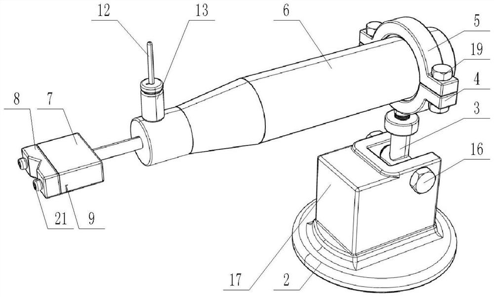
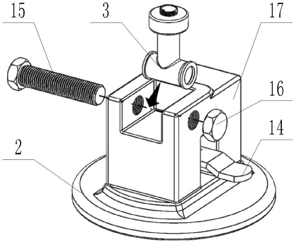
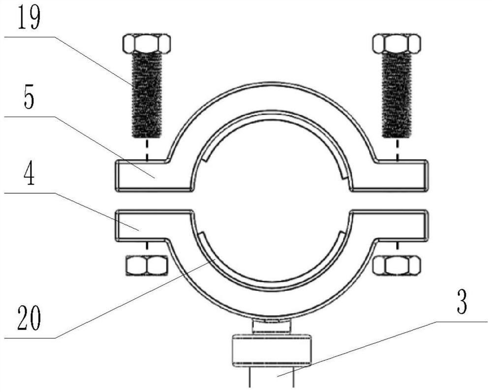
[0045]S2. Obtaining the sample to be etched: the sample is installed on the automatic grinding and polishing fixture, and then the sample is polished to obtain the sample to be etched. Adjust the automatic grinding and polishing fixture, fix the sample on the automatic grinding and polishing fixture, so that the sample is inclined relative to the grinding and polishing plane, and by...

Embodiment 2

[0086] The difference between this example and Example 1 is that in step S2, the clamping method of the sample on the automatic grinding and polishing fixture is different, and in this example, the damage morphology is characterized, and the surface roughness does not need to meet the requirements of EBSD acquisition. Therefore, the polishing process can be omitted, and the fine grinding process can be added. The implementation steps include:

[0087] Obtain slice images of the sample to be characterized after etching: Slice the target area of ​​the sample to be characterized after etching, and obtain SEM images of all slices of the sample to be characterized after etching. After the fine grinding process is completed, the focused ion beam is used to continuously trim the target area of ​​the etched sample to be characterized, and at the same time, use SEM to detect each section after each slice.

[0088] Wherein, the thickness of each slice is preferably set to 50 nm, and it ...


PUM


Abstract

The invention discloses an IGBT chip bonding area microstructure evolution characterization method. The method comprises the following steps: S1, obtaining a sample: preprocessing an IGBT module to obtain the sample; s2, preparing a sample to be etched: mounting the sample on an automatic grinding and polishing clamp, and then grinding the sample to obtain the sample to be etched; and S3, obtaining an etched sample to be characterized: determining a target area of the etched sample to be characterized. According to the invention, the method of etching the bonding area by using the focused ion beam is adopted for sample preparation, so that the EBSD acquisition efficiency is improved, the EBSD image without drift stretching is obtained, and the microstructure of the bonding area is effectively represented; meanwhile, the problems of signal drifting, image distortion and the like caused by the fact that epoxy resin is not conductive and exposed metal parts in devices are reduced in a traditional sample preparation method are solved. In addition, the automatic grinding and polishing clamp is arranged to fix the sample, and the surface flatness and the surface neatness effect of the ground and polished sample are improved.

Description

technical field [0001] The invention relates to the technical field of material microstructure characterization, in particular to a method for characterization of microstructure evolution in an IGBT chip bonding region. Background technique [0002] With the development of the power electronics industry, IGBT modules, as the core power devices for power control and conversion, have been widely used in various occasions. However, during the service process, the IGBT chip is often subjected to repeated impacts of thermal stress, especially the bonding area between the bonding wire and the Al metallization layer, which will undergo microstructural evolution, resulting in degradation of its electrical properties, and eventually leading to failure of the IGBT module. . Therefore, in order to better improve the service reliability of the IGBT module, it is particularly important to study the evolution of the microstructure of the IGBT chip bonding area. [0003] The existing sam...

Claims


Application Information

Patent Timeline
Patent Type & Authority Applications(China)
IPC IPC(8): G01N23/203G01N23/20008G01N23/2251G01N23/2202G01N23/2206
CPCG01N23/203G01N23/20008G01N23/2251G01N23/2202G01N23/2206
Inventor 安彤陈晓萱秦飞
Owner BEIJING UNIV OF TECH
Why Eureka
Try Eureka