Texture structure, optical film, mould and electronic equipment cover plate

An optical film and electronic equipment technology, applied in optics, optical components, branch equipment, etc., can solve the problems of interfering cylindrical mirrors and low pattern resolution, and achieve the effect of reducing influence and flexible light and shadow effects.

Active Publication Date: 2018-11-23
SHINE OPTOELECTRONICS KUNSHAN CO LTD
View PDF7 Cites 2 Cited by
  • Summary
  • Abstract
  • Description
  • Claims
  • Application Information

AI Technical Summary

Problems solved by technology

[0004] The existing decorative textures are generally cylindrical mirrors or printed patterns, and the resolution of the printed patterns is not very high. Second, the use of cylindrical mirrors generally causes rainbow patterns that interfere with the effect of cylindrical mirrors, so it is necessary to develop new decorative textures

Method used

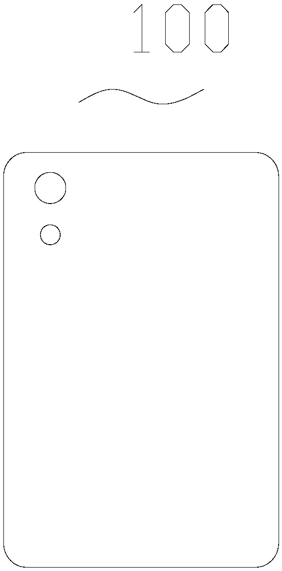
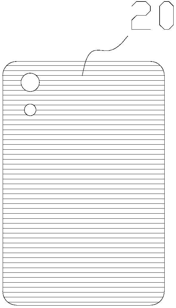
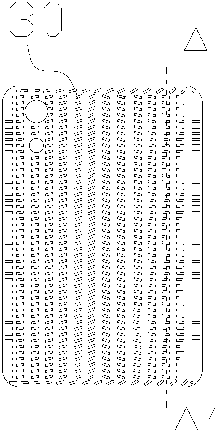

Image

  • Texture structure, optical film, mould and electronic equipment cover plate
  • Texture structure, optical film, mould and electronic equipment cover plate
  • Texture structure, optical film, mould and electronic equipment cover plate

Examples


Embodiment Construction

[0059] In order to facilitate the understanding of the present invention, the present invention will be described more fully below with reference to the associated drawings. Preferred embodiments of the invention are shown in the accompanying drawings. However, the present invention can be implemented in many different forms and is not limited to the embodiments described below. On the contrary, the purpose of providing these embodiments is to make the disclosure of the present invention more thorough and comprehensive.

[0060] It should be noted that when an element is referred to as being “disposed on” another element, it may be directly on the other element or there may also be an intervening element. When an element is referred to as being "connected to" another element, it can be directly connected to the other element or intervening elements may also be present. The terms "vertical," "horizontal," "left," "right," and similar expressions are used herein for purposes o...


PUM


Abstract

The invention discloses a texture structure, an optical film, a mould and an electronic equipment cover plate. The texture structure comprises a plurality of small short lines. An inclined angle is formed between at least one small short line and the horizontal direction. At least one of the small short lines has a convex or concave structure. A space is arranged between the adjacent small short lines. According to the novel texture structure, the direction of the small short lines can be changed at will in a certain direction or according to a desired effect, and the included angle between the small short line and the horizontal direction can vary from 0 to 180 degrees. According to the optical film with the texture structure, the optical film using the texture has at least one light column under a certain light source, and the influence of rainbow patterns on the light and shadow effect is reduced to a certain extent. The electronic equipment cover plate uses the texture structure orthe optical film so that different light and shadow effects of the electronic equipment cover plate can be realized by flexibly using the rotation angle of the small short lines.

Description

technical field [0001] The invention relates to the technical field of textures, optical films and equipment covers, in particular to a texture structure, an optical film, a mold and an electronic equipment cover. Background technique [0002] With the development of science and technology, decorative films are widely used on the surface of electronic products such as mobile phones, computers, household appliances such as refrigerators, air conditioners, washing machines, and automobiles. [0003] Existing decorative films are used as surface materials for mobile devices such as mobile phones and notebook computers, and as surface materials for molding household appliances such as refrigerators, washing machines, and air conditioners. used. [0004] The existing decorative textures are generally cylindrical mirrors or printed patterns, and the resolution of the printed patterns is not very high. Second, when using cylindrical mirrors, rainbow patterns that interfere with th...

Claims


Application Information

Patent Timeline
Patent Type & Authority Applications(China)
IPC IPC(8): G02B1/10B29C33/00H05K5/03
CPCH05K5/03G02B1/10B29C33/00B29C33/424H04M1/0283B29C33/56G02B3/005G02B5/1861B29C33/3857H04M1/02
Inventor 洪莘高育龙亢红伟申溯
Owner SHINE OPTOELECTRONICS KUNSHAN CO LTD
Why Eureka
Try Eureka