Finite element modeling method for binding type generator stator end

A generator stator and stator end technology, which is applied in 3D modeling, electrical digital data processing, image data processing, etc., to achieve the effects of improving modeling efficiency, reducing calculation scale, and being easy to implement.

Inactive Publication Date: 2018-11-23
SHANGHAI ELECTRICGROUP CORP
View PDF5 Cites 4 Cited by
  • Summary
  • Abstract
  • Description
  • Claims
  • Application Information

AI Technical Summary

Problems solved by technology

[0005] In view of the above-mentioned defects of the prior art, the technical problem to be solved by the present invention is a numerical model modeling method of binding complex assemblies on the end of the generator stator and a processing method of key components in the model

Method used


Image

  • Finite element modeling method for binding type generator stator end
  • Finite element modeling method for binding type generator stator end
  • Finite element modeling method for binding type generator stator end

Examples


Embodiment Construction

[0036] In the description of the present invention, it should be noted that, unless otherwise specified and limited, the term "connection" and other terms should be understood in a broad sense, for example, it can be a fixed connection; it can be a disassembled connection; it can also be a point connection; it can be It can be a direct connection; it can be an indirect connection through an intermediary, and it can make the internal communication of two elements. Those of ordinary skill in the art can understand the specific meaning of the above terms in the present invention according to the specific situation.

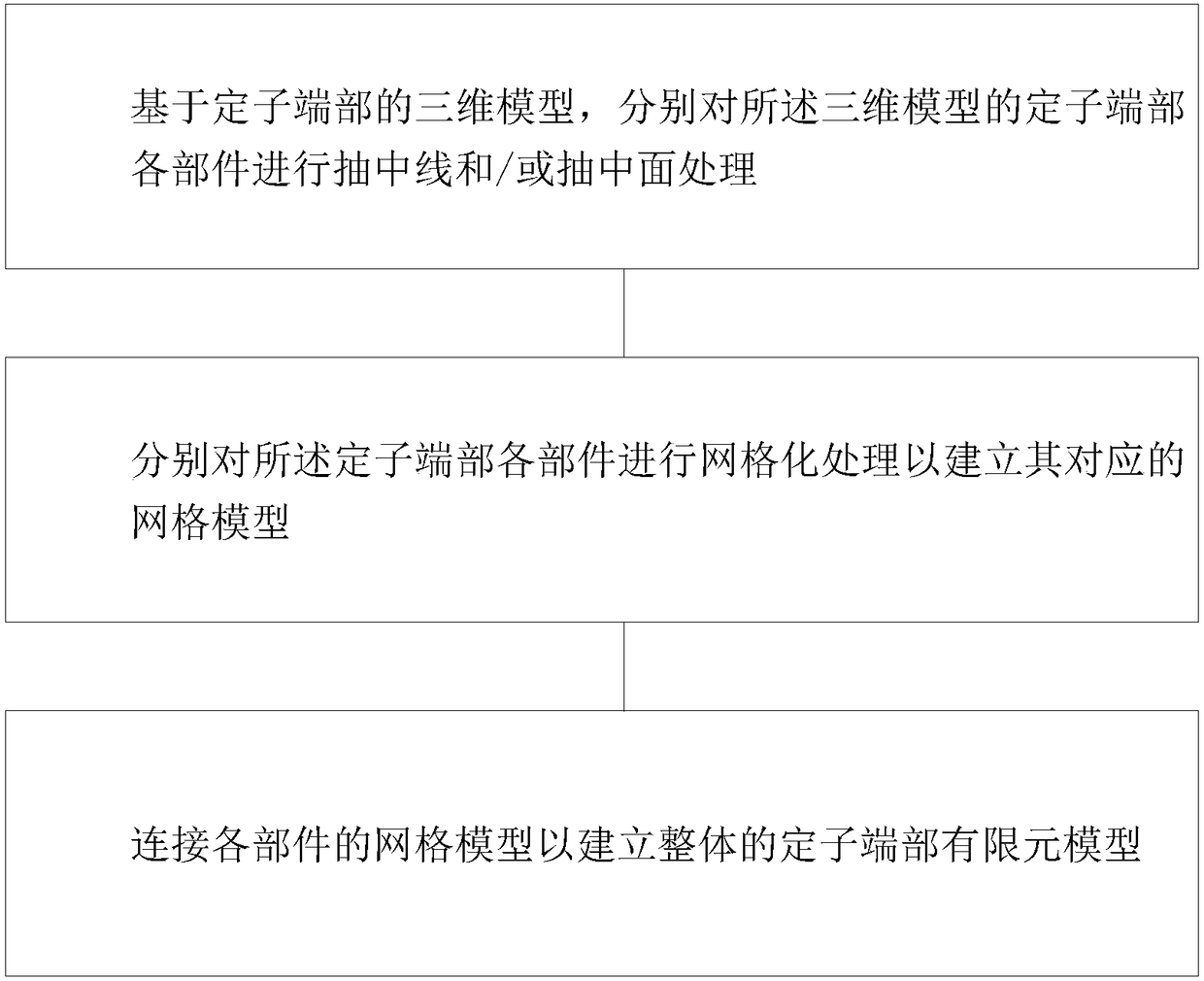
[0037] figure 1 It is a schematic diagram of the finite element modeling method for the stator end of the strapping generator according to the present invention.

[0038] Specifically as figure 1 As shown, the finite element modeling method for the stator end of the strapping generator according to the present invention includes:

[0039] Step 1: Based on the three...


PUM


Abstract

The invention discloses a finite element modeling method for a binding type generator stator end. The method comprises the steps of, on the basis of a three-dimensional model of the stator end, performing middle line extraction and/or middle surface extraction processing on stator end parts of the three-dimensional model; performing gridding processing on the stator end parts to build corresponding grid models; and connecting the grid models of the parts to build a whole stator end finite element model. For the problems that the finite element model in a process of performing dynamics analysison a binding type fixed structure of the generator stator end by adopting a numerical method is difficult to build reasonably and the modeling efficiency is relatively low, on the basis of a principle that beam and shell units is same in degree of freedom, a line rod beam unit finite element model and a bracket and pressing plate shell unit finite element model are built by using middle line extraction or middle surface extraction, and a connection mode of node sharing is adopted, so that the use of contact units is reduced, the modeling efficiency is effectively improved while the modeling difficulty is lowered and the analysis precision is guaranteed, the calculation scale is reduced, and the implementation is easy.

Description

technical field [0001] The invention relates to the field of dynamic numerical analysis, in particular to a finite element modeling method for the stator end of a strapping generator. Background technique [0002] The vibration problem at the end of the stator winding of the turbogenerator has always been one of the difficulties in the research and development of generators. Generally, under normal working conditions, the end of the stator winding of a large generator will be affected by electromagnetic force. Under this electromagnetic force, the stator The vibration at the end of the winding is mainly distributed in an approximately elliptical form, especially when the natural frequency of the components such as the stator end winding of the turbogenerator is close to the electromagnetic force excitation frequency, which will cause damage to the insulation or components on the winding bar, thus affecting the steam. The normal operation of the turbine generator may even cau...

Claims


Application Information

Patent Timeline
Patent Type & Authority Applications(China)
IPC IPC(8): G06F17/50G06T17/20
CPCG06T17/20G06F30/17G06F30/23
Inventor 陈吉刘子娟钱广璞周莹吴新亚张燕杨昔科李新岩
Owner SHANGHAI ELECTRICGROUP CORP
Why Eureka
Try Eureka