Backlight module and manufacturing method thereof

A technology for a backlight module and a manufacturing method, applied in the field of backlight modules and their manufacturing, can solve the problems such as the inability to effectively reduce the thickness, the inability of the luminous keyboard to meet the design requirements of light and thin, the inability to reduce the thickness of the light source circuit board 323, and the like

Inactive Publication Date: 2018-11-23
DARFON ELECTRONICS (SUZHOU) CO LTD +1
View PDF7 Cites 3 Cited by
  • Summary
  • Abstract
  • Description
  • Claims
  • Application Information

AI Technical Summary

Problems solved by technology

[0004] However, there is a technical problem that the thickness of the light source circuit board 323 in the backlight module 32 cannot be reduced. As a result, the current backlight module 32 cannot effectively reduce the thickness, so that the luminous keyboard cannot meet the industry's design requirements for thinner and lighter

Method used


Image

  • Backlight module and manufacturing method thereof
  • Backlight module and manufacturing method thereof
  • Backlight module and manufacturing method thereof

Examples


no. 1 example

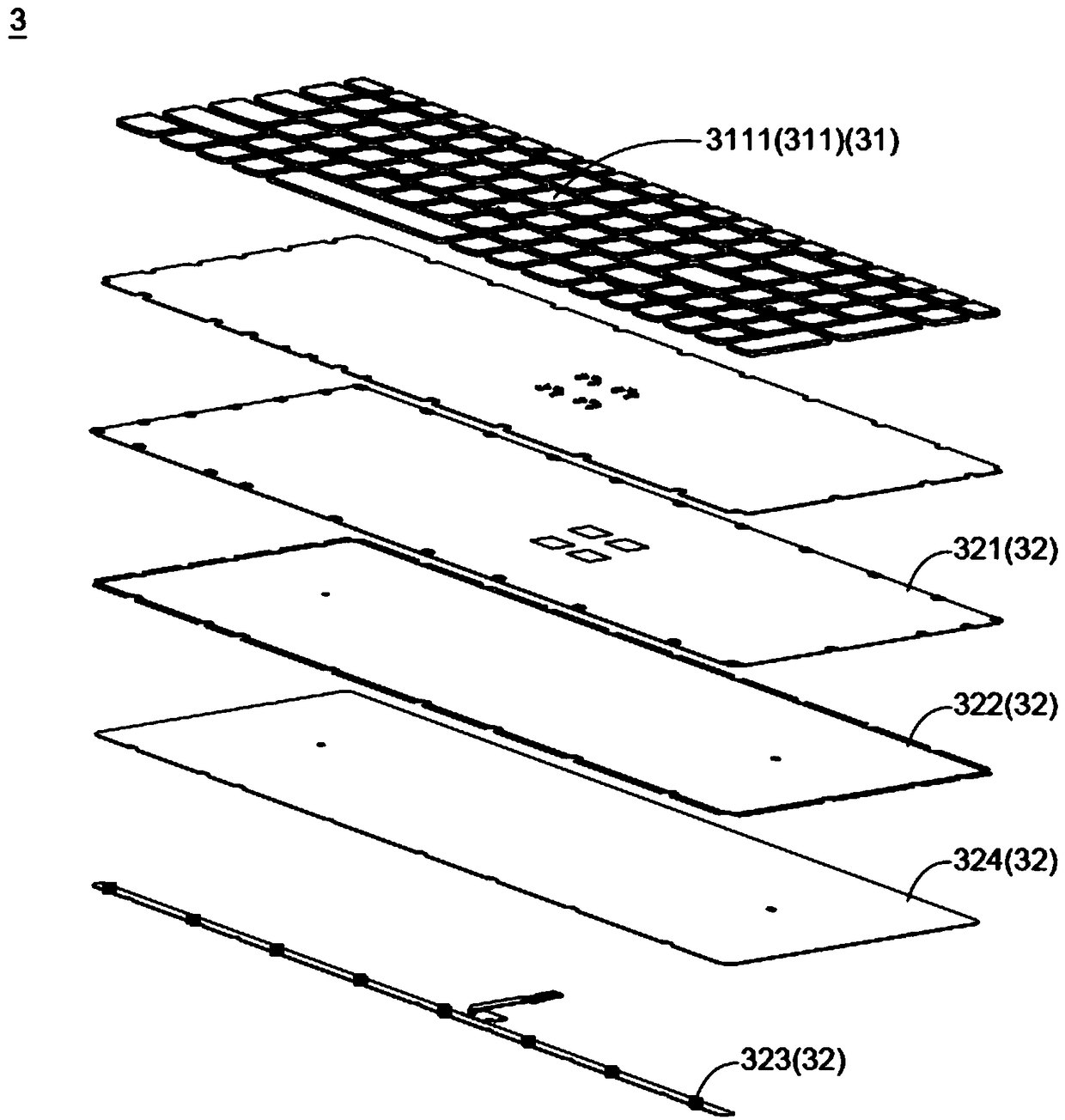
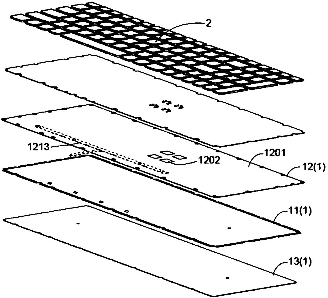
[0033] Please also refer to Figure 2 to Figure 4 , wherein, as shown in the drawings referred to in the left column, the backlight module 1 of the first embodiment is used to provide backlight BL for illuminating a plurality of keycaps 2, wherein there are keycaps between the plurality of keycaps gap. The backlight module 1 of this embodiment includes a light guide plate 11 , a light shielding plate 12 and a reflective plate 13 . The light guide plate 11 is located under the multiple keycaps 2, providing total reflection of the light R inside it, and passing from one end to the other end, and the side of the light guide plate 11 away from the multiple keycaps 2 has multiple scattering structures 111, so The plurality of scattering structures 111 are located under one of the plurality of keycaps 2 respectively, such as concave-convex microstructures or scattering dots, and the concave-convex microstructures may be V-groove structures. In this embodiment, the scattering struc...

no. 2 example

[0044] Please also refer to Figure 5 , wherein, as shown in the drawings referred to in the left column, the biggest difference between the second embodiment and the first embodiment is that the scattering structure 111 of the light guide plate 11 of the backlight module of the second embodiment is arranged on the approach key of the light guide plate 11 The first side of the cap 2 is located below the keycap 2 , and the second side of the light guide plate 11 facing away from the keycap 2 is printed with reflective ink to form a reflective layer 112 of the light guide plate. The position of the scattering structure 111 on the light guide plate 11 destroys the total reflection of the light R in the light guide plate 11, and then scatters the light R in the light guide plate 11, so that the light R can be transmitted toward the keycap 2 and become a backlight BL, so that The light source required for the keycap 2 to emit light is provided. The reflective layer 13 of the light...

no. 3 example

[0047] Please also refer to Figure 6 , wherein, as shown in the drawings referred to in the left column, the reflection plate 13 is arranged on the side of the light guide plate 11 away from the light shielding plate 12, so as to reflect the light R transmitted in the direction away from the light shielding plate 12 and leaving the light guide plate 11, so that The light R returns to the inside of the light guide plate 11 and passes toward the light shielding plate 12 , and the reflection plate can reflect the light R1 leaving the light guide plate 11 back into the light guide plate 11 . The biggest difference between the third embodiment and the first embodiment is that the reflector 13 is provided with a reflector light-emitting element 131 adjacent to the light guide plate 11 . The reflector light-emitting element 131 has a light-emitting surface and can provide light R to the light guide plate 11 .

[0048] To sum up, since the light source of the backlight module of this...


PUM


Abstract

The invention discloses a backlight module and a manufacturing method thereof. The backlight module includes a light guide plate and a light shielding plate. The light guide plate is located under a plurality of key caps and is provided with a scattering structure, and the scattering structure is located below the key caps. The light shielding plate is provided with a light shielding plate body, alight shielding part, a plurality of light exposing parts, a circuit and a light shielding plate light emitting element, the light shielding part and the light exposing parts are located on the side,close to the multiple key caps, of the light shielding plate body, and the circuit and the light shielding plate light emitting element are located on the side, away from the multiple key caps, of the light shielding plate body. The circuit provides electrical energy to the light shielding plate light emitting element, and the light shielding plate light emitting element emits light to the lightguide plate. The backlight module optionally arranges a light source in the light shielding plate or a reflection plate to enables the backlight module not to be needed to be internally provided witha light source circuit board, can further choose the light guide plate of the backlight module to combine the function of the reflection plate to enables the backlight module not to be needed to be internally provided with the reflection plate, and the backlight module can reduce the number of components to reduce the thickness and conforms to the requirements of the industry for the lighting andthinning of the backlight module.

Description

technical field [0001] The present invention relates to a backlight module and a manufacturing method thereof. Specifically, the present invention relates to a backlight module capable of omitting a light source circuit board and a manufacturing method thereof. Background technique [0002] The keyboard is an indispensable accessory for computer use. When the keyboard is operated in a dim environment with low light intensity, the user may not be able to clearly see the identification symbols marked on the keycaps of each key on the keyboard, which makes it difficult for the user to operate the keyboard. [0003] Therefore, some people have designed light-emitting keyboards, and due to the gradual popularization of light-emitting keyboards, users have increasingly strict requirements on the functions of light-emitting keyboards. see figure 1 , figure 1 It is a schematic diagram of main layers of a conventional luminous keyboard. Such as figure 1 As shown, the conventiona...

Claims


Application Information

Patent Timeline
Patent Type & Authority Applications(China)
IPC IPC(8): H01H13/83G02B6/00
CPCH01H13/83G02B6/0011G02B6/0055H01H2219/06H01H2219/062H01H2219/064
Inventor 黄恒仪何信政陈在宇
Owner DARFON ELECTRONICS (SUZHOU) CO LTD
Why Eureka
Try Eureka